I wanted to mount my GPS without having cables all over the place or having it somewhere that doesn’t seem well-integrated. Fortunately, the overhead console in the Discovery is a perfect location. The real advantage is that the device is hidden from obvious view outside the car, so thieves won’t be tempted by it.

My wife and I picked a Disco S7 because it didn’t have sunroofs. Since I keep cars and trucks for a long time it seemed a bad idea to get something with more parts to go bad. The other advantage is that the panel for the sunroof buttons is blank.
The other goal is to add a backup camera. Our Garmin Nüvi 65 supports the BC-30 backup camera, and I’ll cover installation of that unit in a separate post.
So, how do you mount this thing?
Mise en Place
See, it’s like a recipe, get it? So, here are the tools and hardware you’ll need:
Hardware:
- GPS Bracket Mount
- Thin, long bolt with a shallow head
- Nut and washer for bolt
- Quick splice connectors
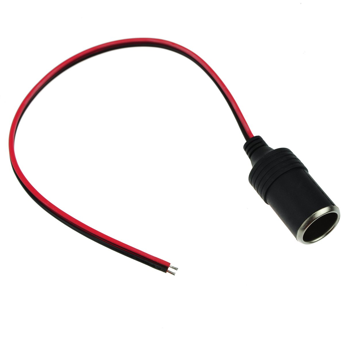
- Cigarette lighter female power socket
Tools:
- Plastic spreader or putty knife to remove panel
- #2 Philips screwdriver
- Wrenches for bolt and nut
- Drill and drill bits
- Hobby knife
- Hobby glue (E.g., CA glue, Krazy Glue)
- Pliers to attach quick splice connectors
- May also need:
- Multimeter
- Unibit for drilling power supply hole
Step 1: Select a Mount
I first considered using Velcro, but there are two problems with that:
- Modern Garmins have a rounded back.
- The backing tape on Velcro eventually goes bad. If your GPS is mounted on the ceiling then it will eventually fall off on a hot day.
Instead, use the slimmest mount designed for your unit. For most Nüvi models you only need the bracket mount.

Attach the GPS to the mount and find a good location on the overhead console for it. Remember to include enough clearance so you can unmount the device. (I forgot to take a picture of this step.)
While holding the GPS in the desired location, mark where the bracket meets the panel with a pencil.
Step 2: Temporarily Glue the Mount to the Panel
Remove the sunroof blanking panel from the console using a plastic spreader or putty knife.
Note: For folks with a sunroof I imagine you could relocate the switches somewhere else, if you really want to mount a GPS like this.
Next, use CA glue (Krazy Glue) to attach the bracket to the panel. This is just to keep the parts together while you drill later on.
Step 3: Drill Holes for a Bolt
Select a thin bolt that is long enough to go through both the bracket and the panel. I used a 1/4″-20 bolt because they were handy. 4mm-.7 would also work fine.
You want a bolt with as shallow a head as possible, so a hex head is probably your best choice.
Drill holes through the center of the bracket and on into the panel to fit your bolt.

You can see on the picture above the glue didn’t hold. That’s fine—you just need it to hold enough to get the pilot hole drilled.
Step 4: Bolt Bracket to Panel
Run your bolt through both the bracket and panel.

Then, check the clearance of the bolt head and the face of the bracket. If the bolt head isn’t flush or below the surface, then you will need to grind the head down.

The image above shows the bolt after some light grinding with a Dremel.
Attach the bolt and add a washer and nut. I recommend using some Loctite to keep the nut in place.

You’ll note in the picture that I cut away a portion of the raised plastic support. This is easily done with a hobby knife as the plastic is quite soft.
Step 5: Cut a Hole for the Power Cord
This wouldn’t be that great without power, so cut a hole to fit the cord.
I cut a square hole using a drill bit and the hobby knife. In retrospect I wish I had made a door rather than a hole. (Again, I forgot to take a picture.)
To cut a door simply identify how large the hole needs to be, then cut 3 walls at a 45 degree angle away from the center of the hole. Then, cut the plastic on the fourth wall about halfway through.
Or just cut a big enough hole for the cable. The only real disadvantage of this approach is that dust can get in the overhead console.
Step 6: Test Fit the GPS
Replace the panel in the console and test fit the GPS. Hopefully everything’s fine.

Step 7: Add a Cigarette Lighter Socket
The GPS power supply requires switched 12VDC power. While you could theoretically use a hardwired USB cord, I recommend using a power socket and the GPS’s power supply. This allows you to more easily replace it in the future and you get the added advantage of the power supply’s voltage regulators. Garmin GPSs seem to be sensitive to voltage fluctuations, so using their power adapter is a good idea. (Also, Garmins sometimes put features in the power supply—for example, the BC-30’s receiver.)
Remove the panel again and look for the wires going to the rear view mirror. If you can reach them, great. If not you may need to remove the overhead console—it’s quite easy to unscrew.
There are two wires you want:
Green/White for switched power
Black for ground

Notes:
- This is true for an ’03 Disco. If other years use different colors then you’ll have to use a multimeter to find the right wires. That’s easy enough to do—it’s how I figured out which wires to use.
- I originally used the green/brown wire, as shown in the picture. This is a mistake as that’s the reverse circuit. This could be very useful if you use a wired camera because you can tap into the reverse right inside the console.
Use quick splice connectors as shown above to connect a cigarette lighter socket. You can find the splices at any parts store, but here’s an Amazon link. The cigarette lighter socket might be harder to find, but you can buy an extension and cut off the ends. Conversely, here’s one on Amazon.
Step 8: Test the Power
Before you button everything up, give the connections a quick test. Attach the power supply and turn on the ignition. If the supply doesn’t work, check the wiring with a multimeter.

It’s a bit hard to see because the test lead is in the way, but the power supply’s LED is lit.
You really shouldn’t hang the overhead console by the light wires like I did. But really, who cares. It’s not heavy and the connectors are pretty robust.
Step 9: Tuck the Power Supply in the Console
Wrap the excess cord around the power supply to give some cushioning and wrap that in electricians tape.

Then, tuck the whole thing in the console.

Step 10: Finish
Place the panel back and mount the GPS. You should be good to go!

Coming up next: Adding a back up camera.