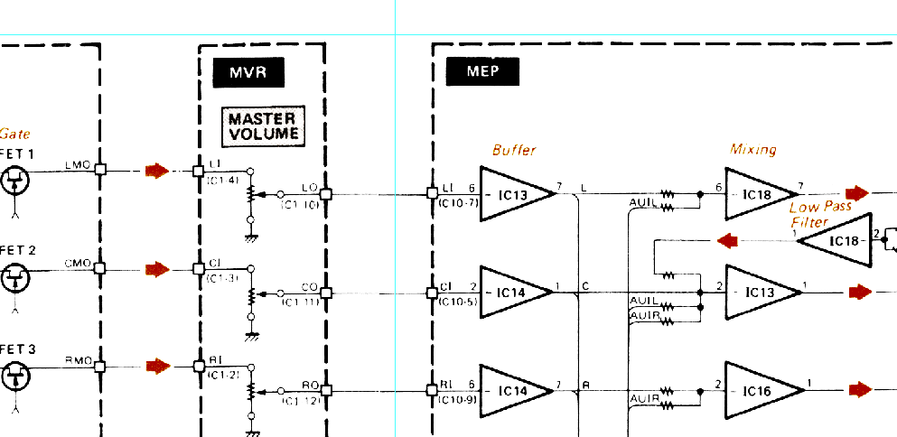
Scanning in these Yamaha FX/FS schematics has been a real chore. But I’ve come up with a pretty solid method that goes relatively quickly and produces nice results.
This approach groups all of the processor-intensive steps in the beginning to make it much easier to do the fine-tuning adjustments without waiting on the computer’s processor.
Scan the Whole Schematic to High-Res Files
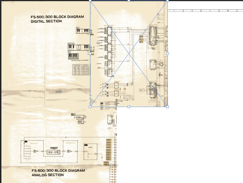
First, scan as large the entire schematic in as large of sections as possible at 1200 dpi (2400 is overkill).
Most importantly, INCLUDE OVERLAP!
Your schematics are probably folded and you will be tempted to scan based on the folds. But that means the art that goes around the folds will never be scanned correctly.
Instead, scan larger areas that overlap.
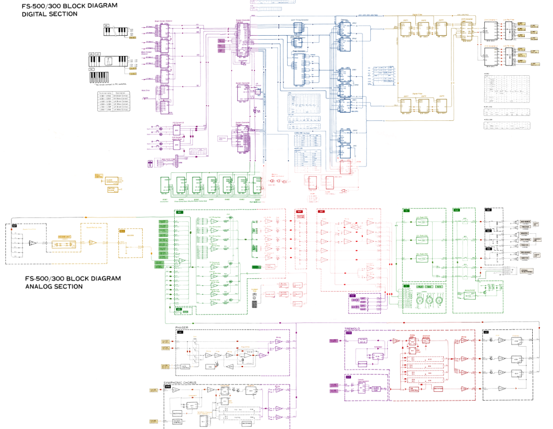
The screenshot below illustrates this. Notice that the scan highlighted by the blue bounding box includes some of the other page that has been scanned.
Arrange the Scans in Photoshop
Make an artboard that is the size of the original full schematic. Create a white background layer and lock it.

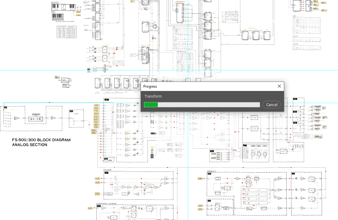
Roughly arrange all the scans in Photoshop so they align pretty well. It doesn’t need to be perfect yet, but you can use the Transform tool to rotate as needed. Don’t worry about warping or stretching yet.
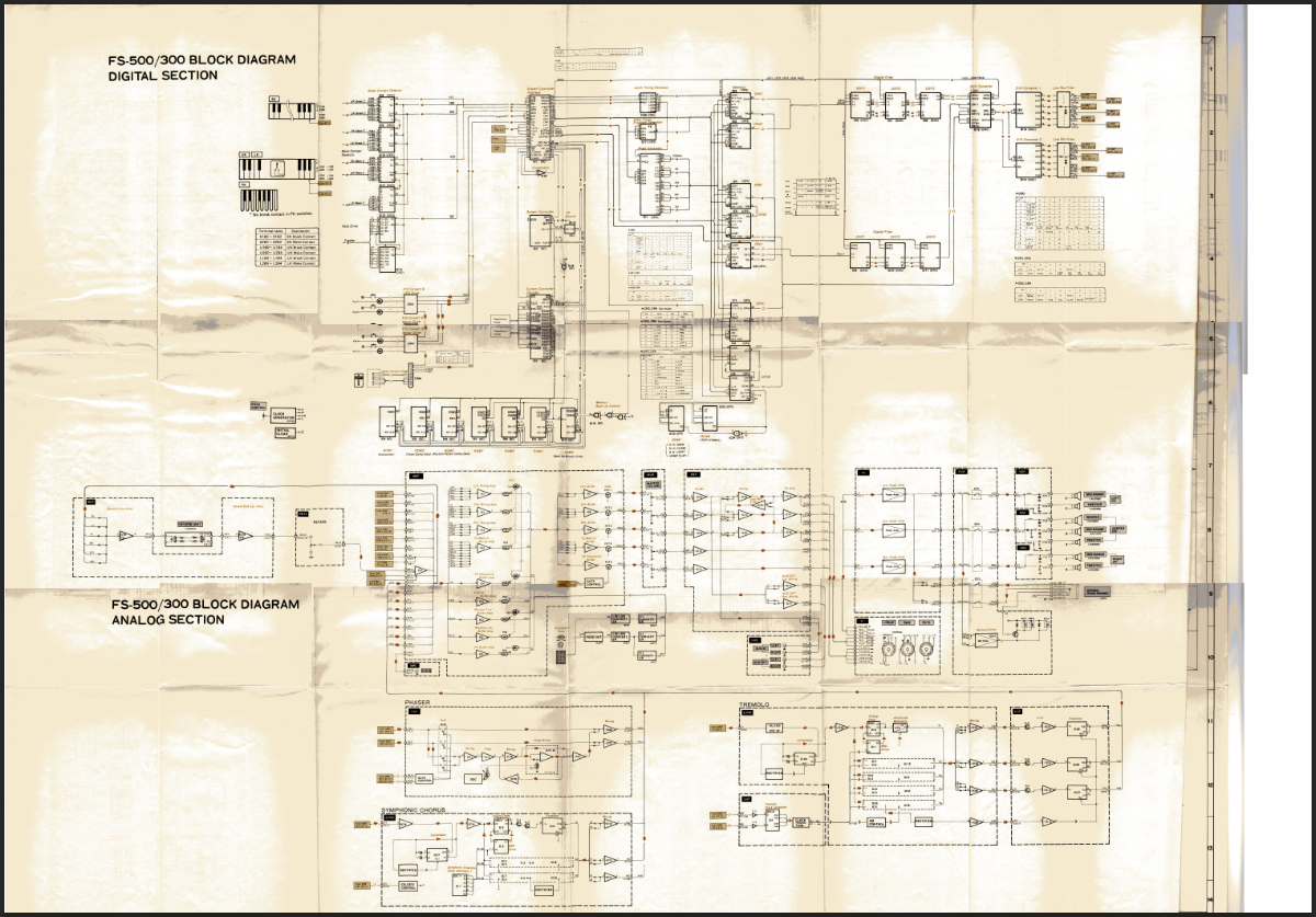
In the image above you can see some of the overlapping of the scans. There is about an inch of overlap on all sides except the left. This is the edge I am using as my baseline on the scanner.
Save your file. You will likely need to use the .PSB large file format.
Apply First Round of Color Correction
Applying color correction now will make it much easier to stitch the scans together later on. This will end up being a black and white image with selective color using masks.
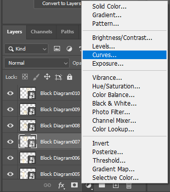
Ctrl-Select the center-most image. (Mac users… do whatever the equivalent is.) Then, create a new Curves adjustment layer.
Adjust the curve to remove any yellowing or shadows from the folds. You want the text and lines to be as crisp as possible. You might lose some definition in colors, if present, but we can adjust for that later.
After adjusting the curve, save the curve.
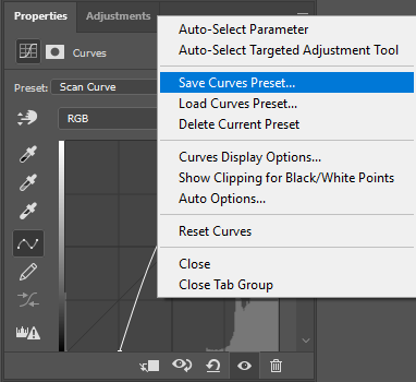
Then, repeat the above process for each layer except load the curves preset you just created.
You might ask why not just apply one curve layer over all the scans rather than this more time-consuming approach. Later on we will merge layers together which works better with individual curves.
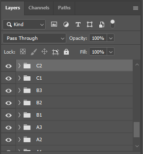
Move to Groups
Each scan and its respective adjustment layers will eventually be merged. Before that you will need to group the scans and layers into folders. Now is as good a time as any.
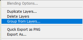
Tip: Give the group layers a name that identifies their location on the artboard. In the example below I’m using Excel-like cell coordinates.
Apply Second Color Correction
Add a Black and White adjustment layer above the Curves layer.
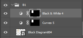
If your schematic has any color in it then it will be gone:
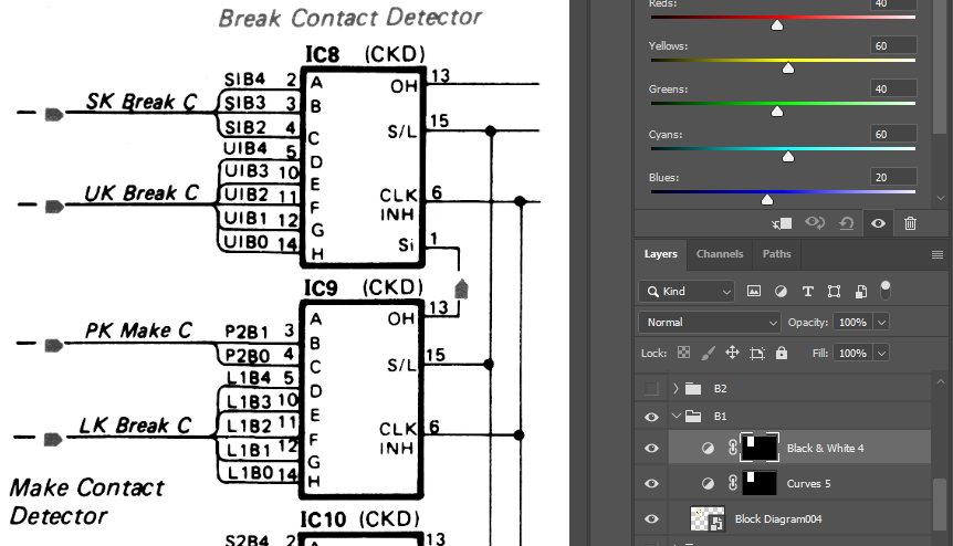
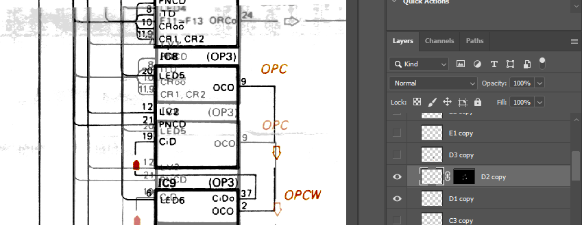
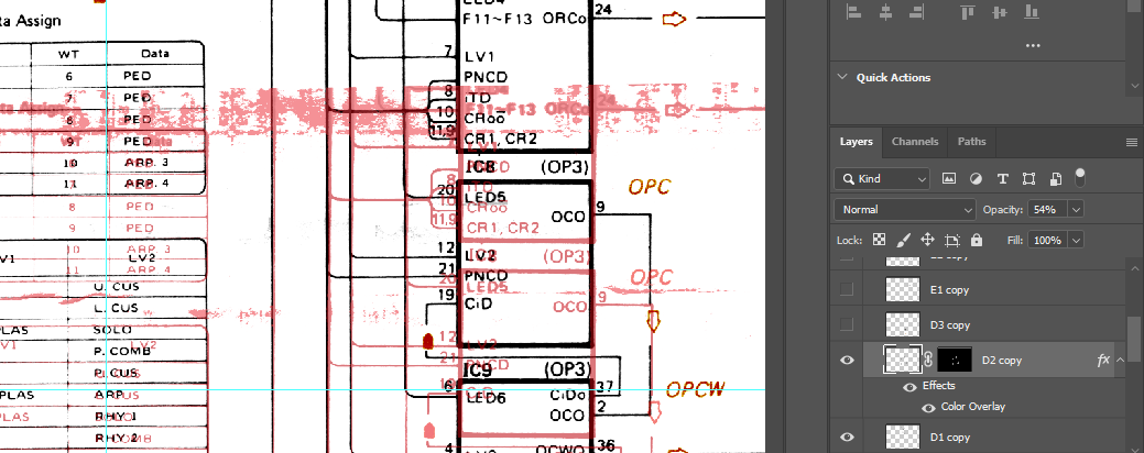
Use a black brush on the layer mask to bring the color back only where it’s needed. Below is a screenshot of this process half-way through.
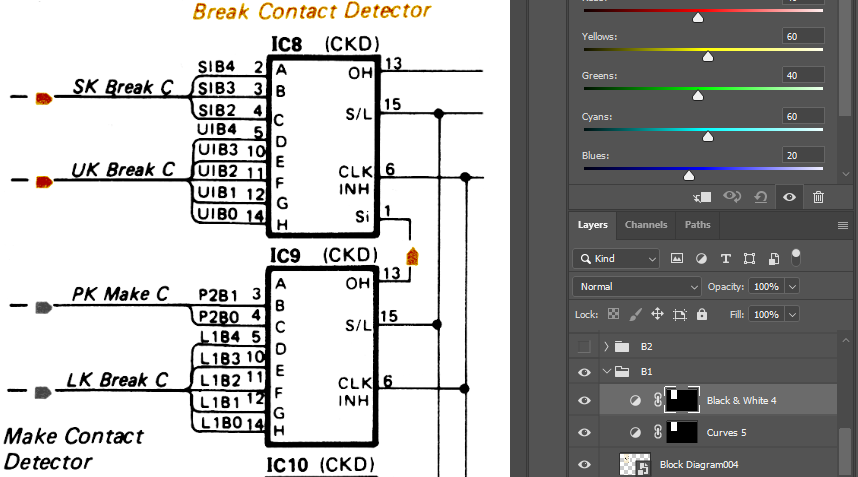
It’s a good idea to enable and disable the B&W adjustment layer to make sure you didn’t miss anything.
It should be starting to look pretty decent:
At this point you can also clear up obvious blotchy areas that won’t be used, but it will probably be easier later on.
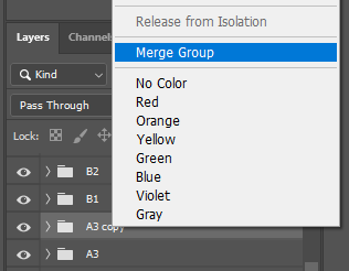
Duplicate and Merge Groups
Duplicate each group and then merge them. It’s up to you if you change the name or leave it with “copy”. I leave it because it makes it easier to track your work.
Why duplicate the groups? Because we’re going to save the originals in a backup file and delete them from the working file. This makes the file much smaller and easier to work with.
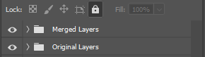
Move Merged Layers to New Group
Select all the merged layers and move them to a new group. You can also move the old layers to a different group.
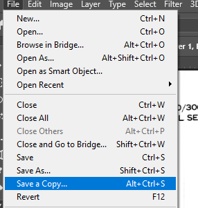
Save a Copy then Delete Original Layers
To reduce the processor overhead we will drop the original layers by saving them into a backup and then deleting them. Save a Copy of the Photoshop file.
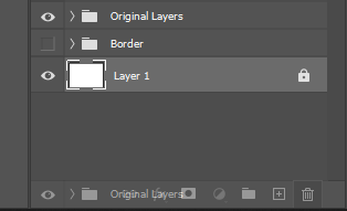
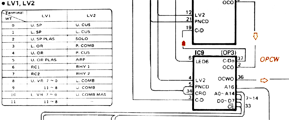
Then delete the original layers and save the file. (Note: The Border layer in my schematic is a left-over from another scan that I will need again. It is not related to this tutorial.)
Delete White Space
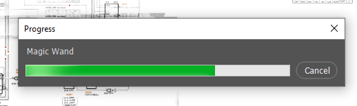
Use the Magic Wand on each merged scan to select the white space. Be sure the Contiguous box is not checked. Set the tolerance relatively low (32 in this example). Then, delete (clear) it.
Disabling the white background makes it easier to see what you need to complete.
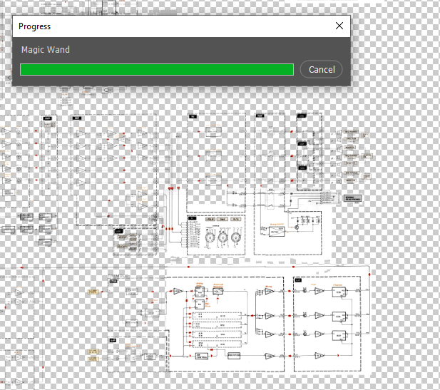
Now you can easily see where the scans overlap. We can being stitching everything together.
Before that, save your file. It is a good idea to close Photoshop and open it again to clear the cache.
Begin Stitching Layers
Start with the centermost scan. Hide all layers except that one.
It’s not a bad idea to straighten this scan out using transform.
Pick an adjoining layer to stitch and enable it.
Make sure the first layer is above the one you will edit. Add a color overlay and reduce opacity to about 50%.
Select the layer you are going to edit and apply a Free Transform.
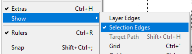
Tip: It’s a good idea to hide the Marching Ants by going to View > Show > Selection Edges.
Align the layer as best as possible then commit the Free Transform.
Use the brush tool and masks to remove the overlap. You may need to blend the layers a bit, but this can easily be done with a 100% hardness brush if you stitch where lines connect.
You also may need to use Warp in small sections.
Disable the layer color effect and reset opacity to 100% to make sure everything looks right. It should now look like one image.
Continue in this manner until all layers are stitched.
Tip: Apply differently colored overlays to help identify which layer’s content to keep.
If you use multiple colors then it should look something like this when you’re done:
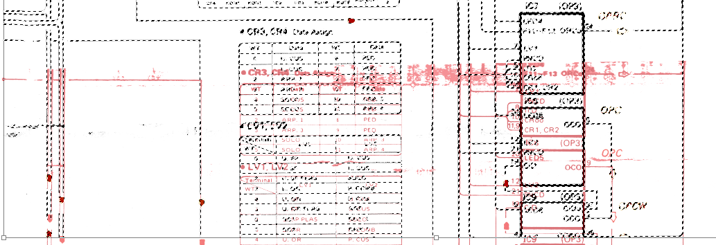
You can make global adjustments to the group containing all the layers. For example, all the layers can be straightened out.
Resize and Save to New File
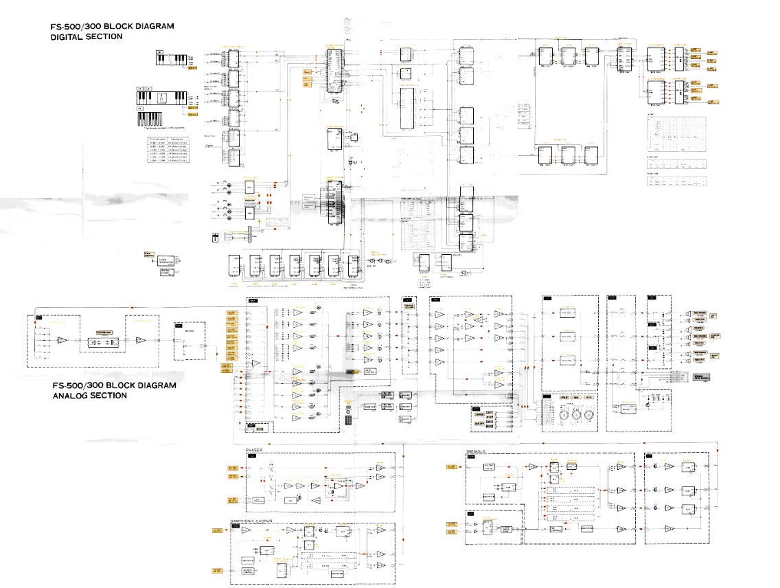
Save your current file first. Then, resize the image to something more manageable on screen. For example, this scan was originally 40″ wide and has been resized to 20″.
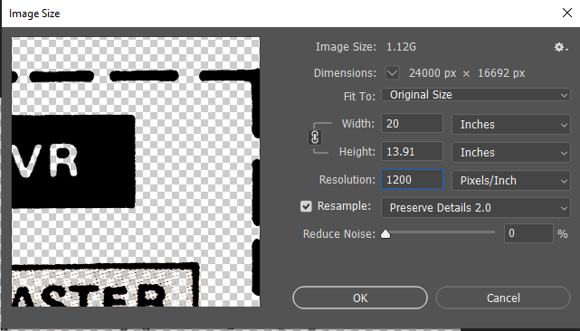
Why resize now instead of earlier? While resizing earlier makes the image easier to work with, it also makes it significantly harder if you need to grab content from the backup or add new scans for mis-scanned content.
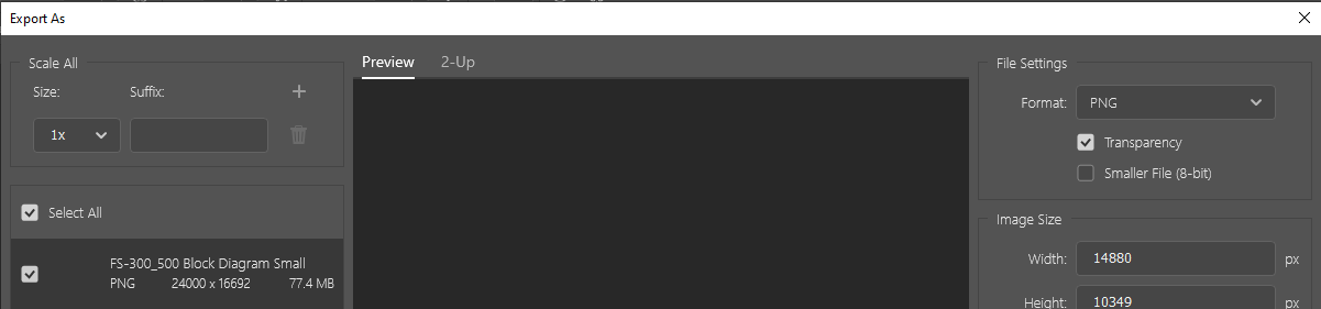
Export As
Now you can export from this file to whatever file type you prefer. I am using PNG with transparency.
Convert to PDF (or not)
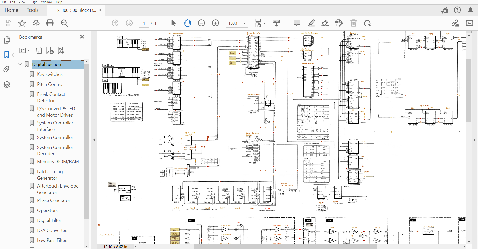
I suggest converting the PNG to a PDF, especially since it is the standard for viewing schematics. You can also add bookmarks to make it easier to navigate. You may also scale the PDF down one more level. There should be more than enough dpi left to make this much smaller.
You’re done!