If you have a K250 then you also have (or have had) a dead or dim screen. They’re all that way. But now, thanks to the magic of buying things, you can have a screen that’s visible, even in the dark! Oh frabjous day!
Here is the original display in mine versus the new one:
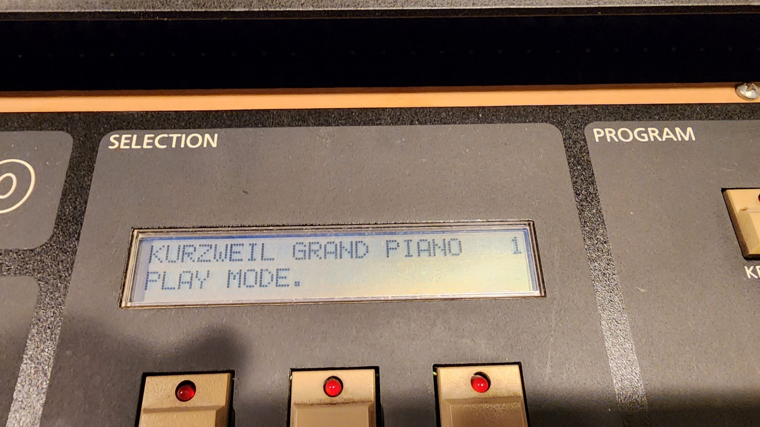
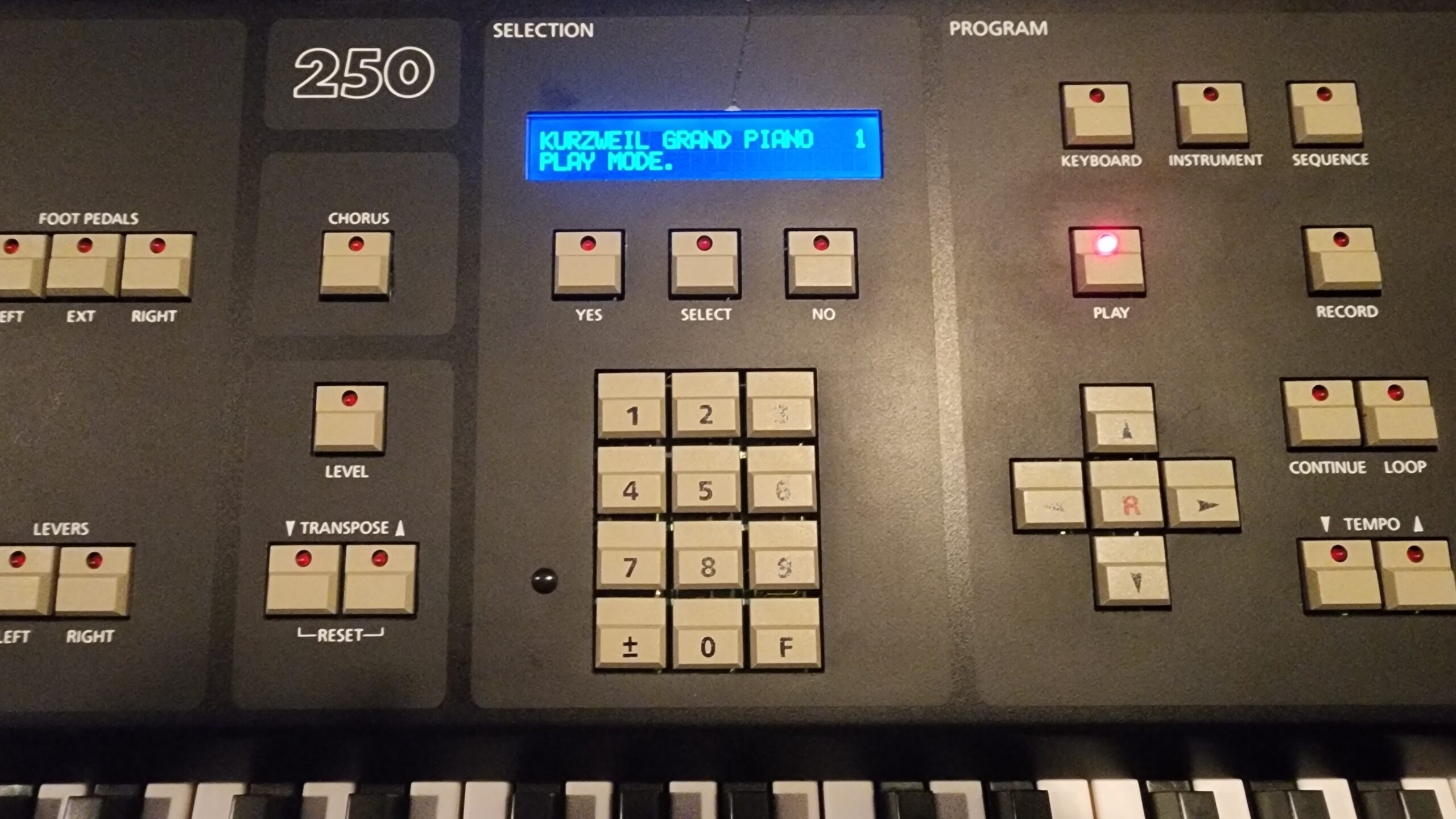
The phone’s camera makes it appear blurrier than it is. In person it’s crisp and easy to read.
The replacement is pretty easy. You will need a display meeting the following specifications:
- Type: 24 x 2 character LCD display
- IC equivalent: HD44780
- Controller: 6800 4-bit parallel (or 4/8 bit parallel)
- Power Supply: 5V
- Character Set: English/Japanese
- Dimensions: 118mm x 36mm
The one I used is available here from BuyDisplay.com as of the time of writing. Since URLs get updated often and this site doesn’t, you may need to look for a display meeting the requirements above.
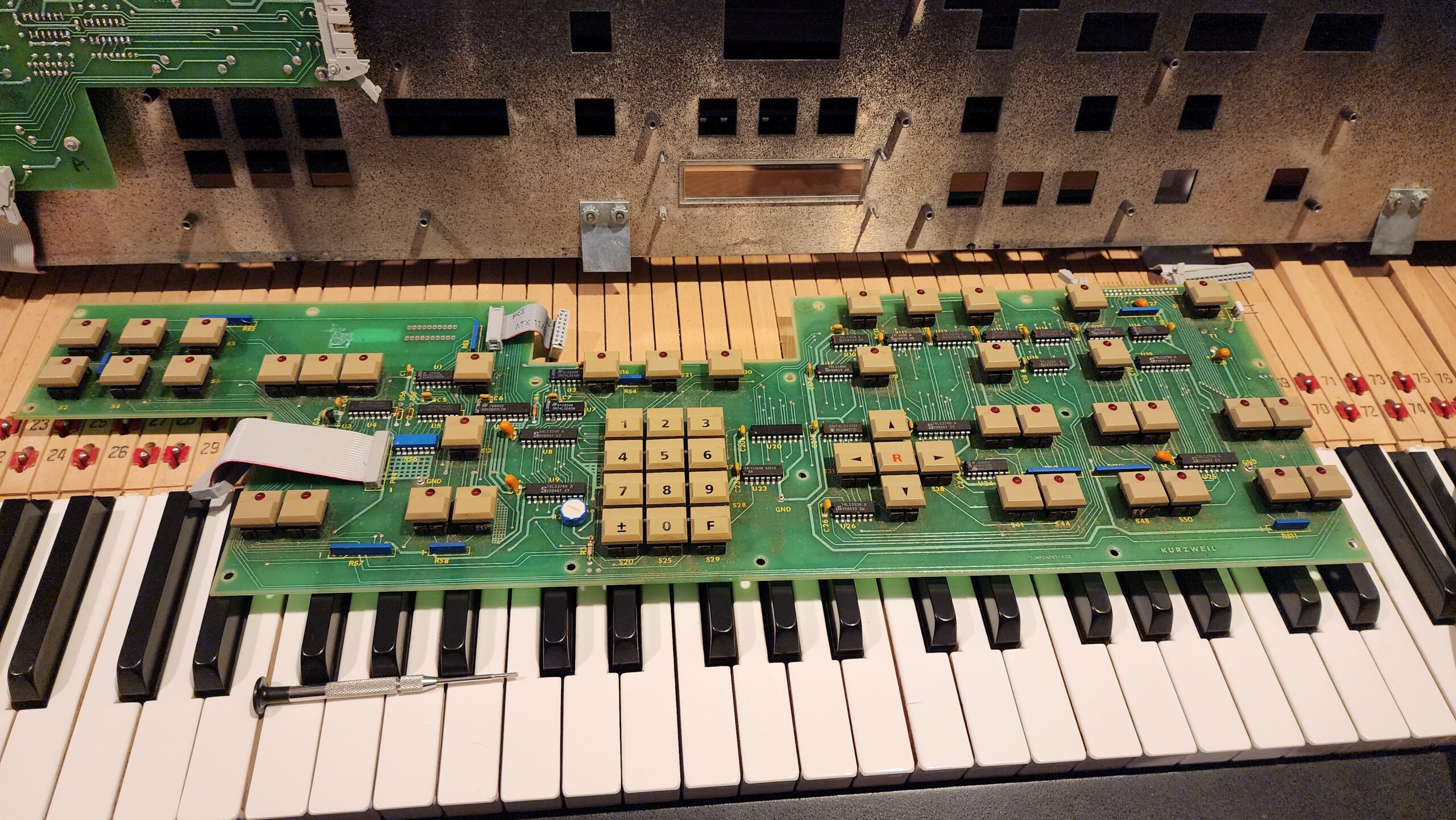
Step 1: Remove the display and control panel
Loosen the two screws on the front panel and lift into the service position.
Disconnect all three cables going to the control panel (you can leave the slider board in place). Remove all the screws securing the control panel, and remove the board.
Disconnect the backlight connector from the display, then unscrew the display and remove it. Be careful not to lose the nuts and washers!
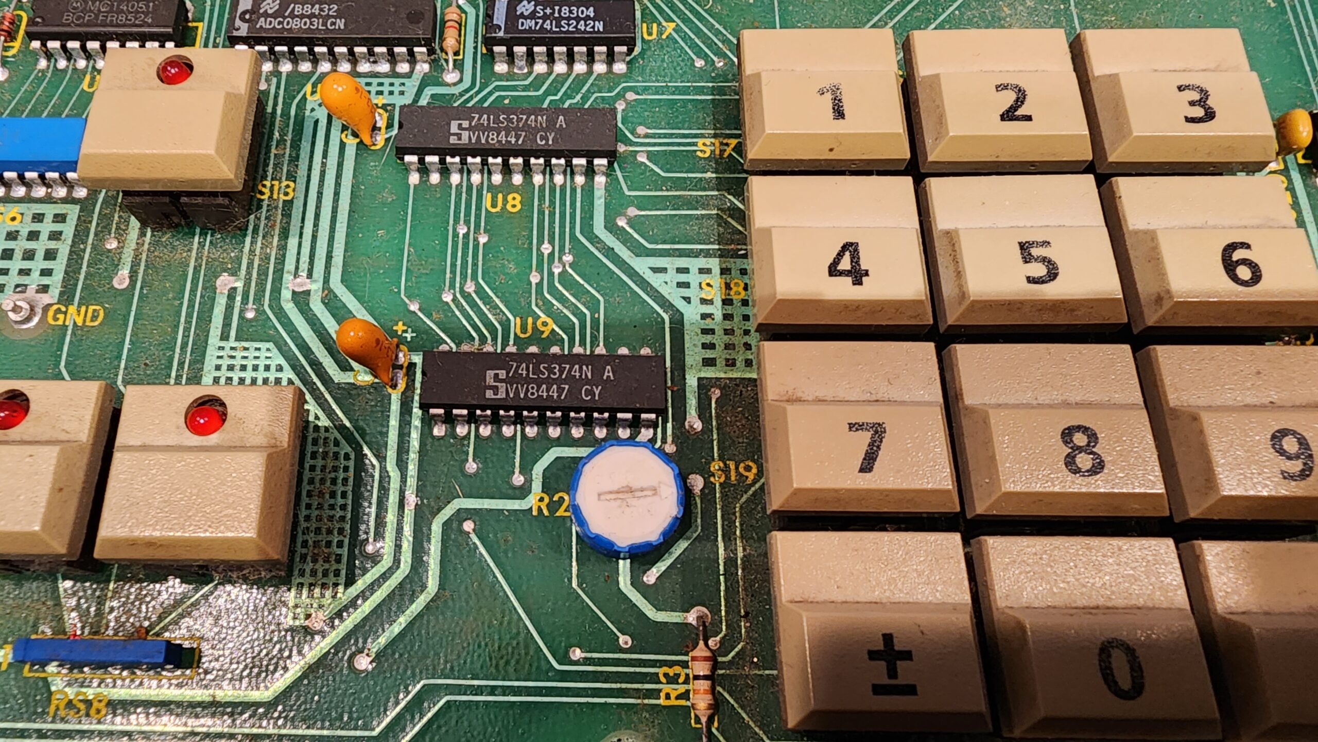
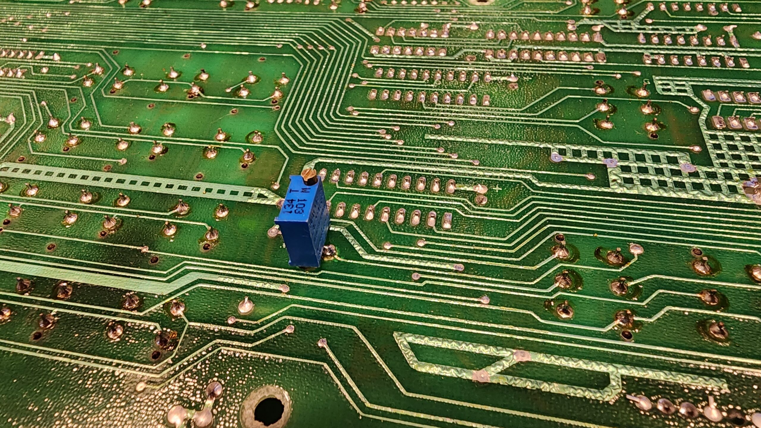
Step 2: Decide whether to move the contrast trimmer
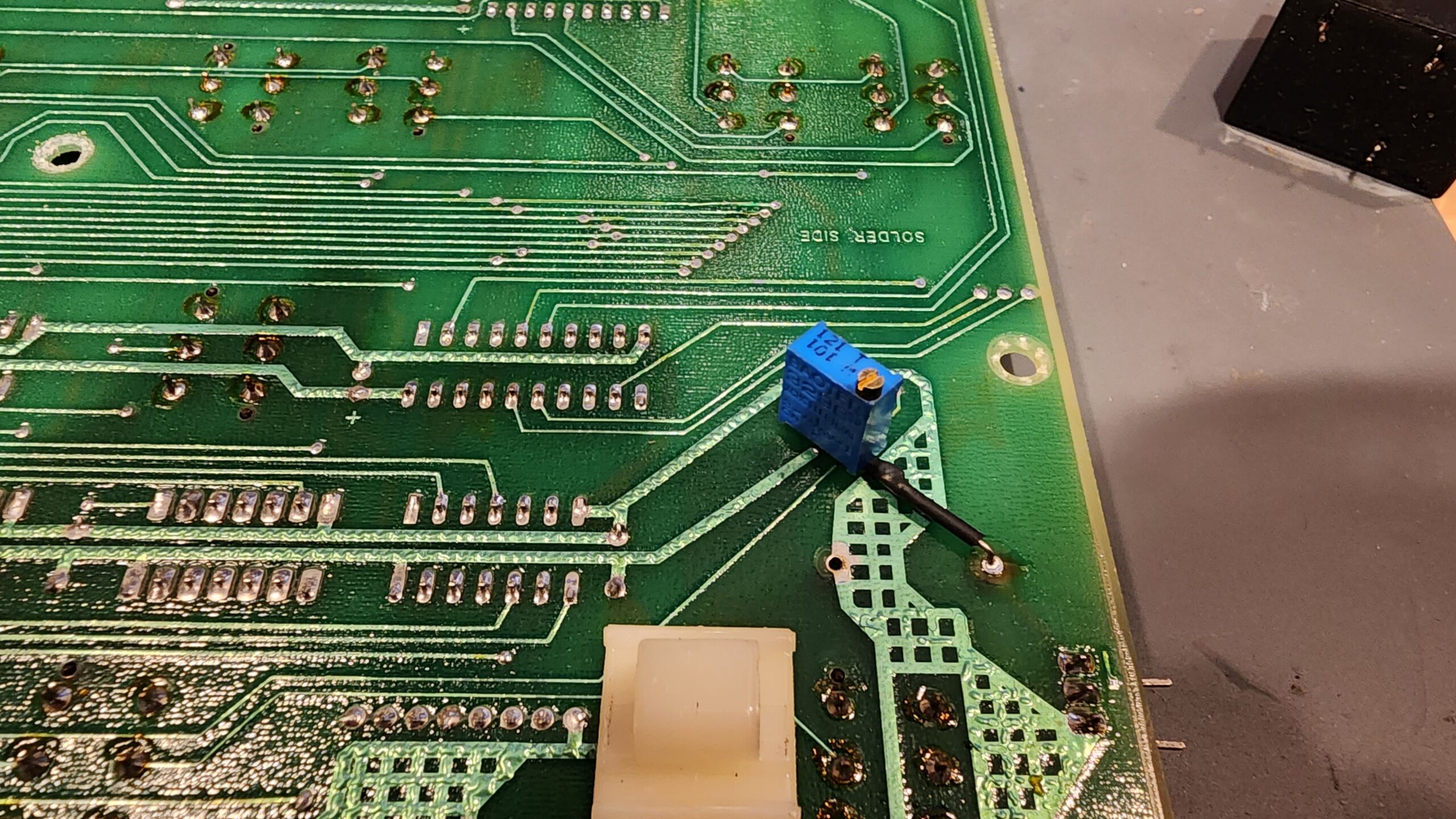
The contrast trimmer, shown below, is accessible from the front panel by removing the round cap near the 7 button. Personally, I hate it because it’s hard to remove without scratching the panel. I flipped my trimmer to the back of the circuit board to make it easier to adjust.
This is not an important thing to do! In many ways, this is probably a pointless step so you can choose not to do it. But if so, here’s what you do:
Desolder the old trimmer. Mine had its leads bent in such a way that I mangled the circuit board and the trimmer. So I just replaced it with a new 10k multiturn pot. Before installation, set the new trimmer to roughly the same resistance as the old one. If you don’t know it, it’s probably about 5k ohms.
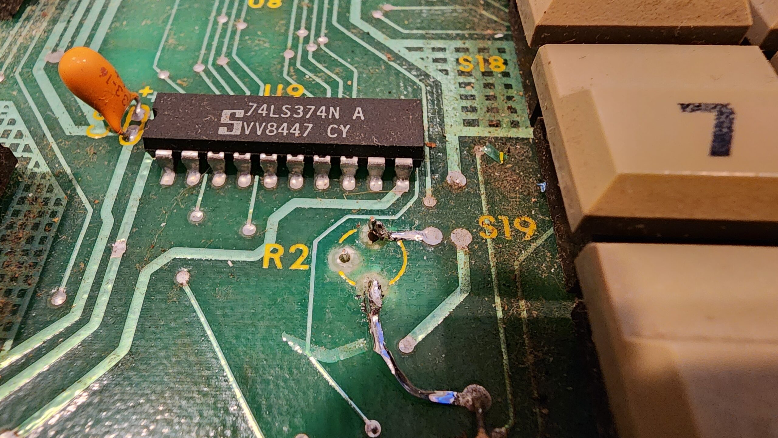
As you can see above, the traces were damaged when I removed the old trimmer.
I’m still glad I did this because I don’t like that plastic cover, but again, you do you.
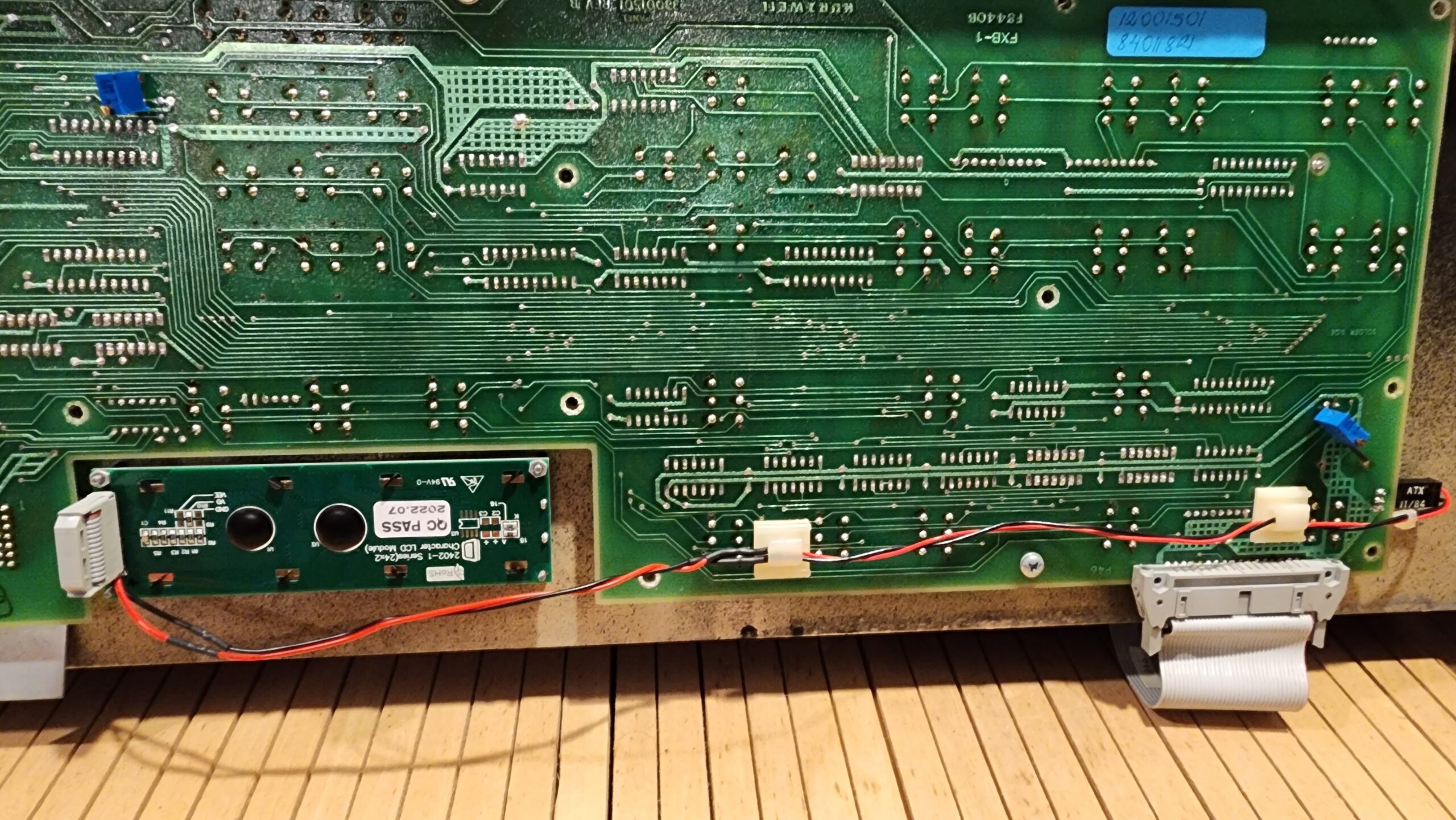
Step 3: Remove the backlight inverter and add a trimpot for the backlight
The old backlight inverter is no longer needed. The good news is that you can reuse the wiring for the new backlight and the inverter’s power supply. You will need to add a trimpot to dial back the brightness on the backlight.
De-solder and remove the inverter. It’s the big black box on the right side of the panel.
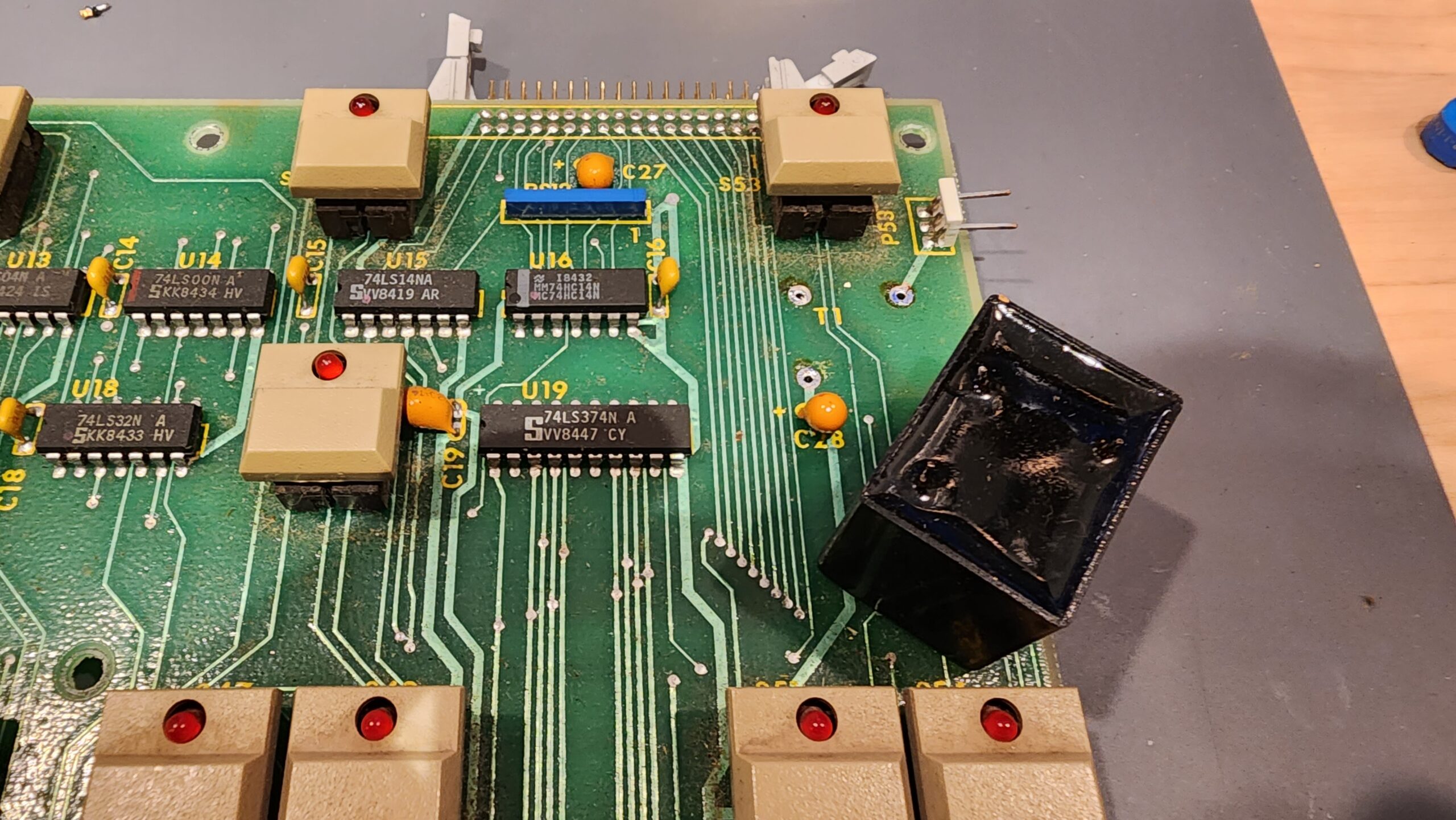
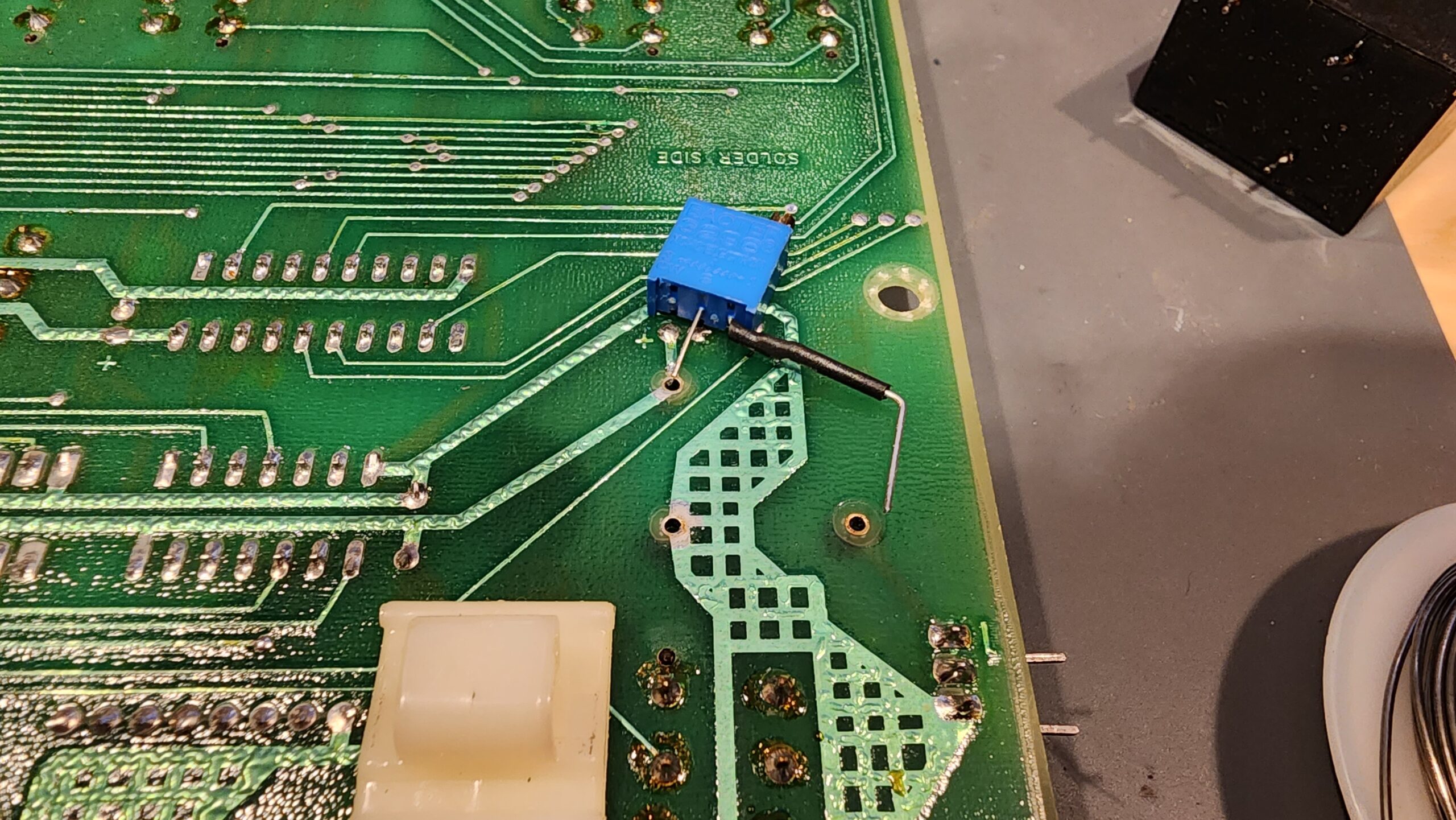
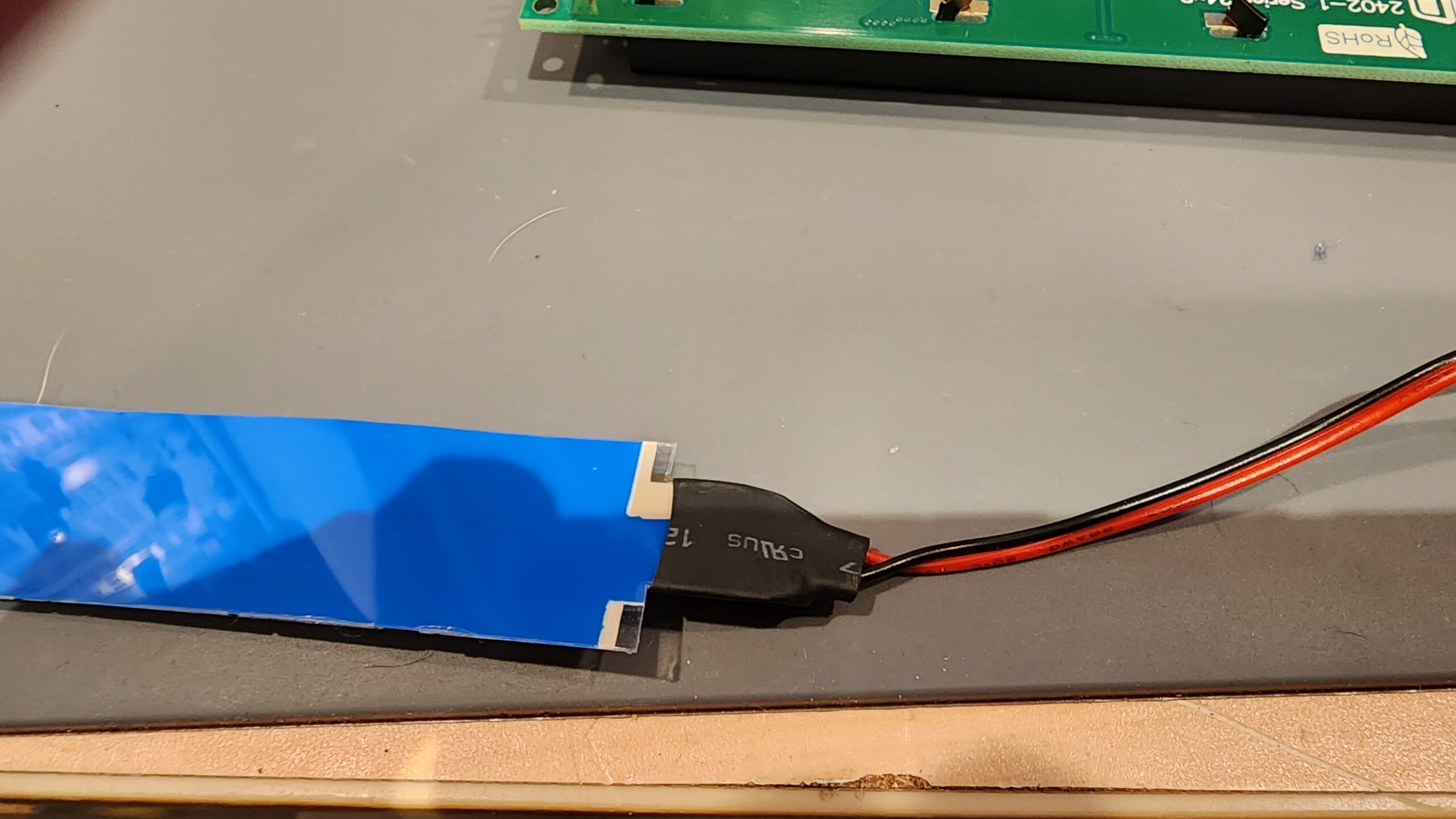
Fashion a new 100-500k ohm trimpot to go between the + side of the tantalum and pin 1 of the old backlight connector. I used a 100k ohm pot which is fine, but I think 250k ohms would be better.
NOTE: Pin 1 should connect to the red wire, but Kurzweil sometimes made mistakes. Be sure you connect the red lead to pin 1.
In the image below you can see where the leads will go, and that the section of lead that crosses the grid-shaped ground trace has heat-shrink insulation to prevent shorting.
Step 4: Cabling
Either add a header to the new display for pins 1-14 or, if your display came with one pre-installed, remove pins 15 and 16. I chose pre-installed because it’s easier.
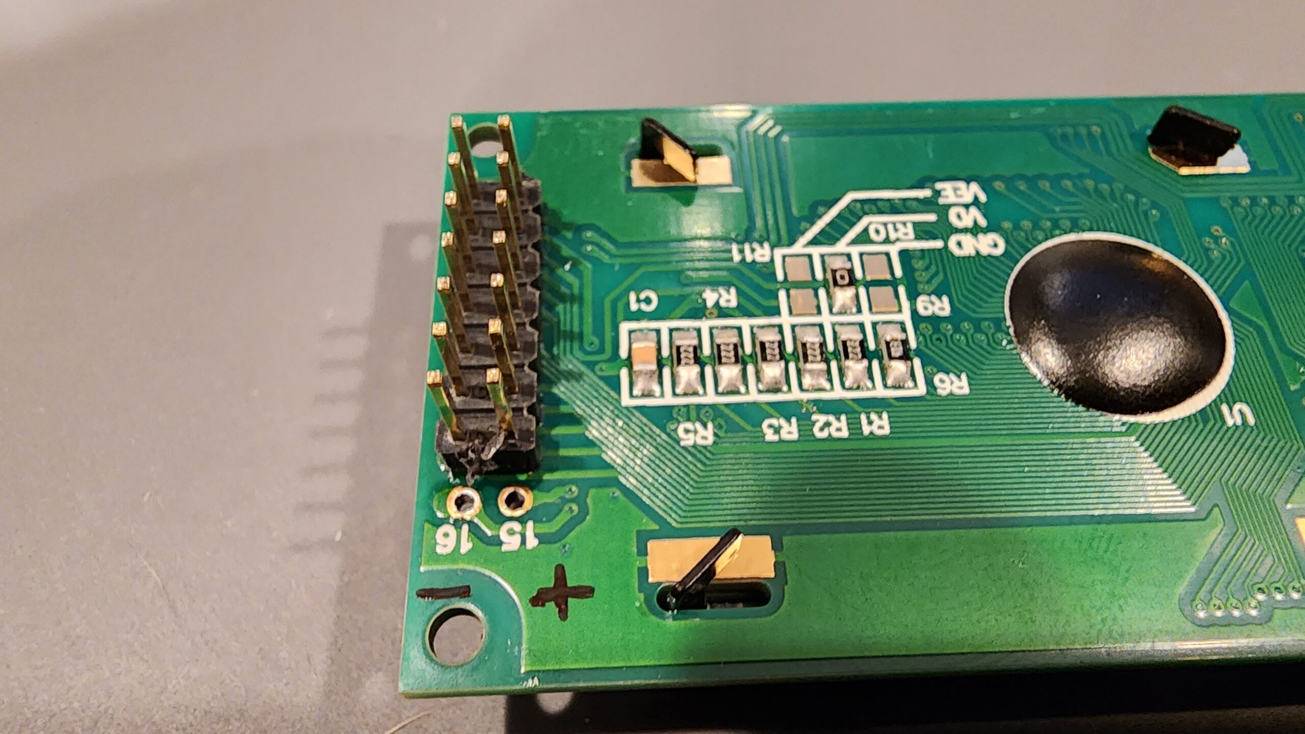
Clip the leads to the old backlight and solder red to pin 15 and black to pin 16 on the display. I’ve marked them positive and negative in the image above.
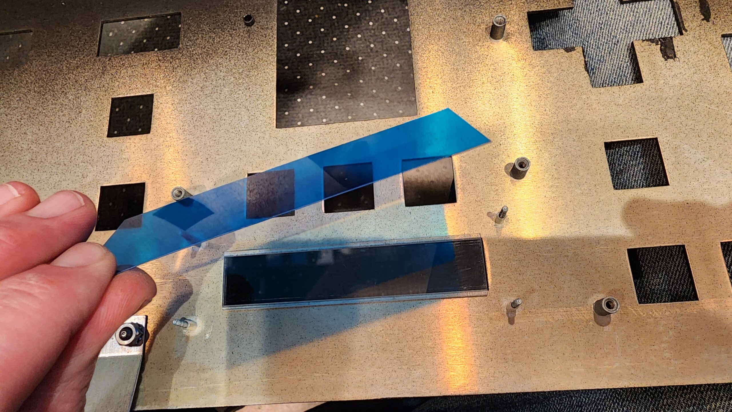
Step 5: Optional – Add a blue filter
I added a blue filter to smooth out the display. It’s nice, but not critical.
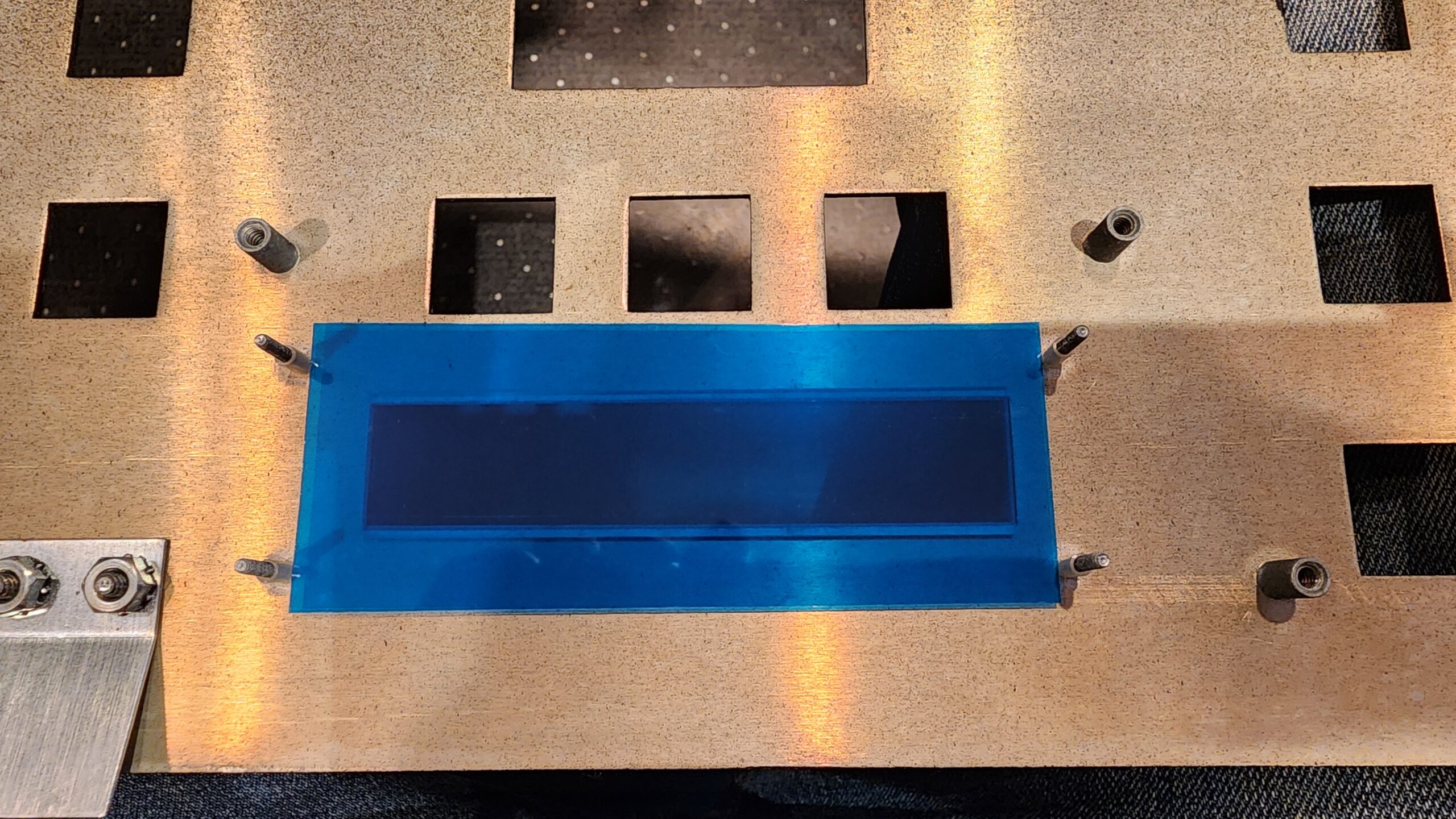
Step 6: Reinstall and adjust
Reinstallation is very straightforward. You can install a few screws on the panel and a couple nuts on the display for testing. It should look something like this:
You will probably need to adjust the backlight and contrast. If the display is just showing a string of fully illuminated boxes, then the contrast is too high.
Once everything is working, install all the other screws, nuts, and washers, close it up, and admire your work!
A Good Thing To Do: Replace the Tantalum Capacitors
While you have the board out, it’s a good idea to replace the two 10uF 35V tantalum capacitors where the big connectors go to the panel. These can short and kill the board, or worse, kill the synth.
If you do that, then also pull the slider board and replace the two tantalums there as well.