This guide was made for my E-70, but from what I can tell this is pretty much valid for any Electone using the big spinning foam thing that is similar to a Leslie lower drum.
If your tremolo unit is running intermittently or not at all, then this guide is likely to help.
Please pardon how dark some of these photos are. It’s pretty dark down there without a flashlight.
Removing the Tremolo Unit
Remove the speaker and panel above the pedalboard. It’s just three screws and a connector.
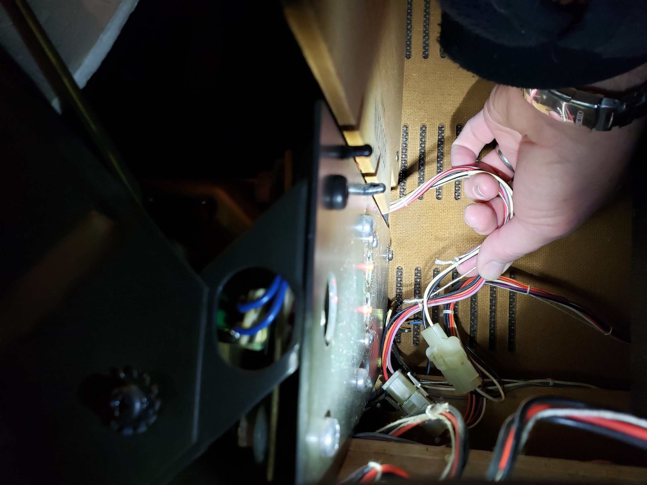
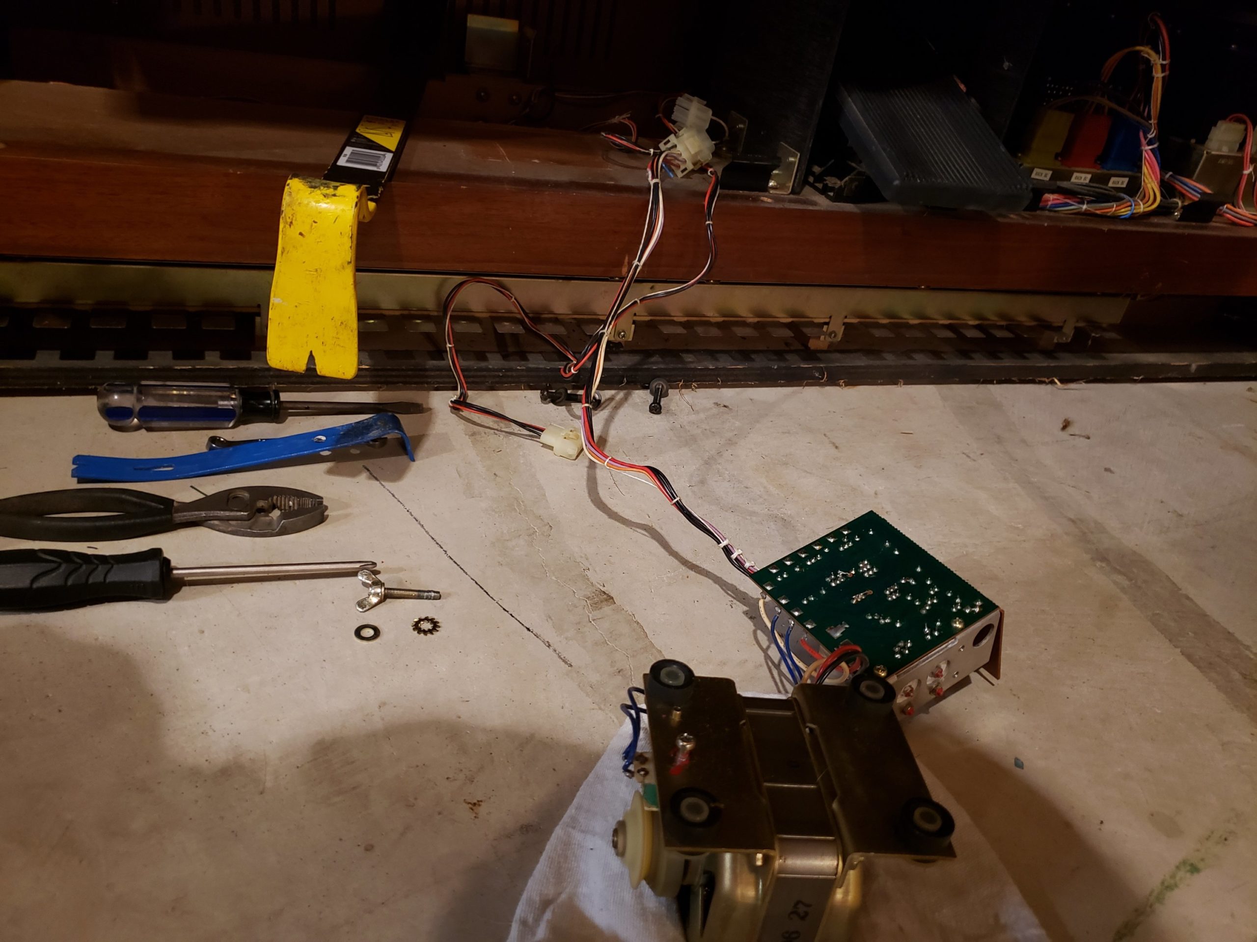
First, disconnect the plugs going to the tremolo unit. These are held in place with wire ties.
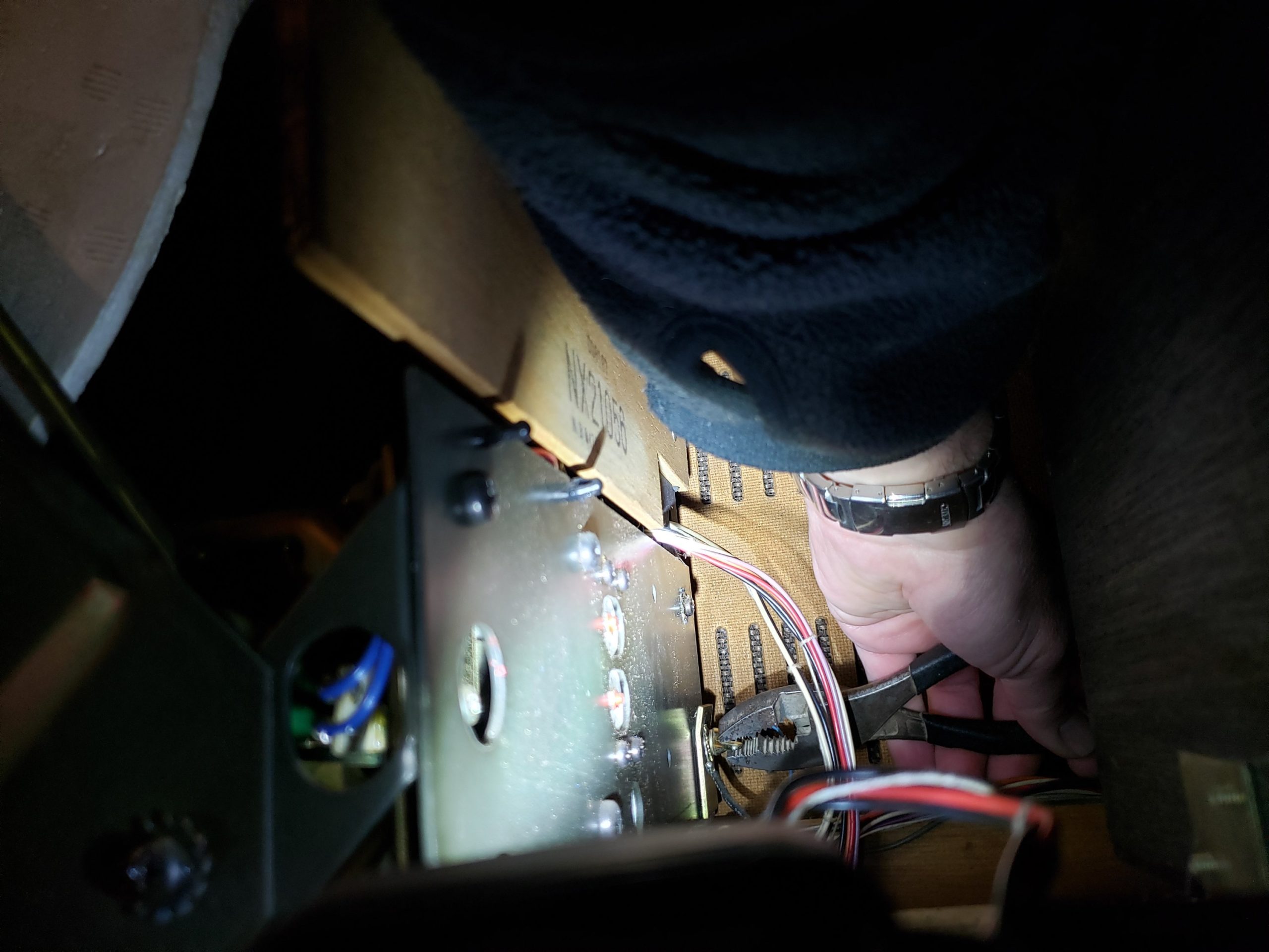
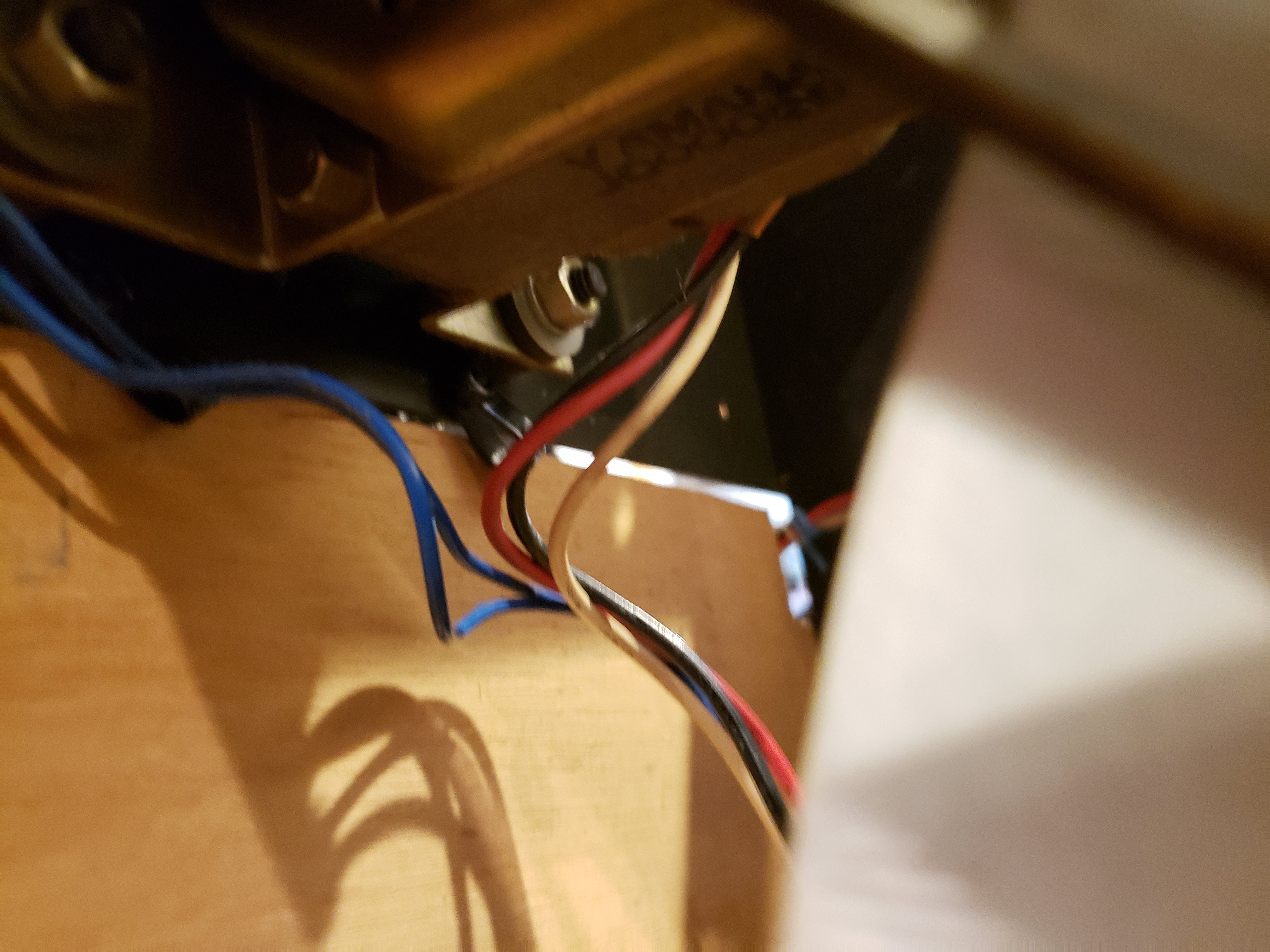
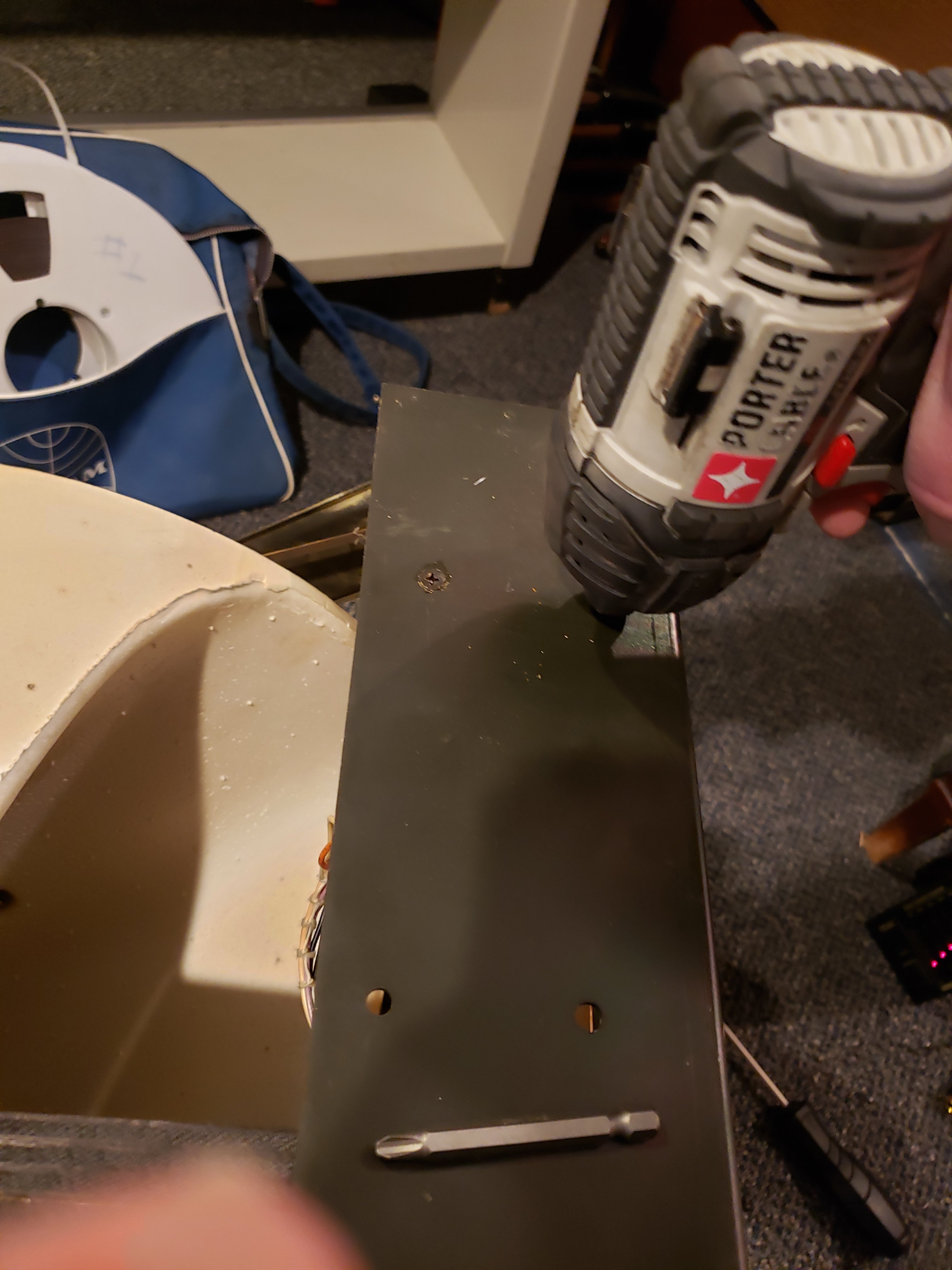
Then, remove the wingscrew holding the unit in place. I’m pointing at it in the photo below.
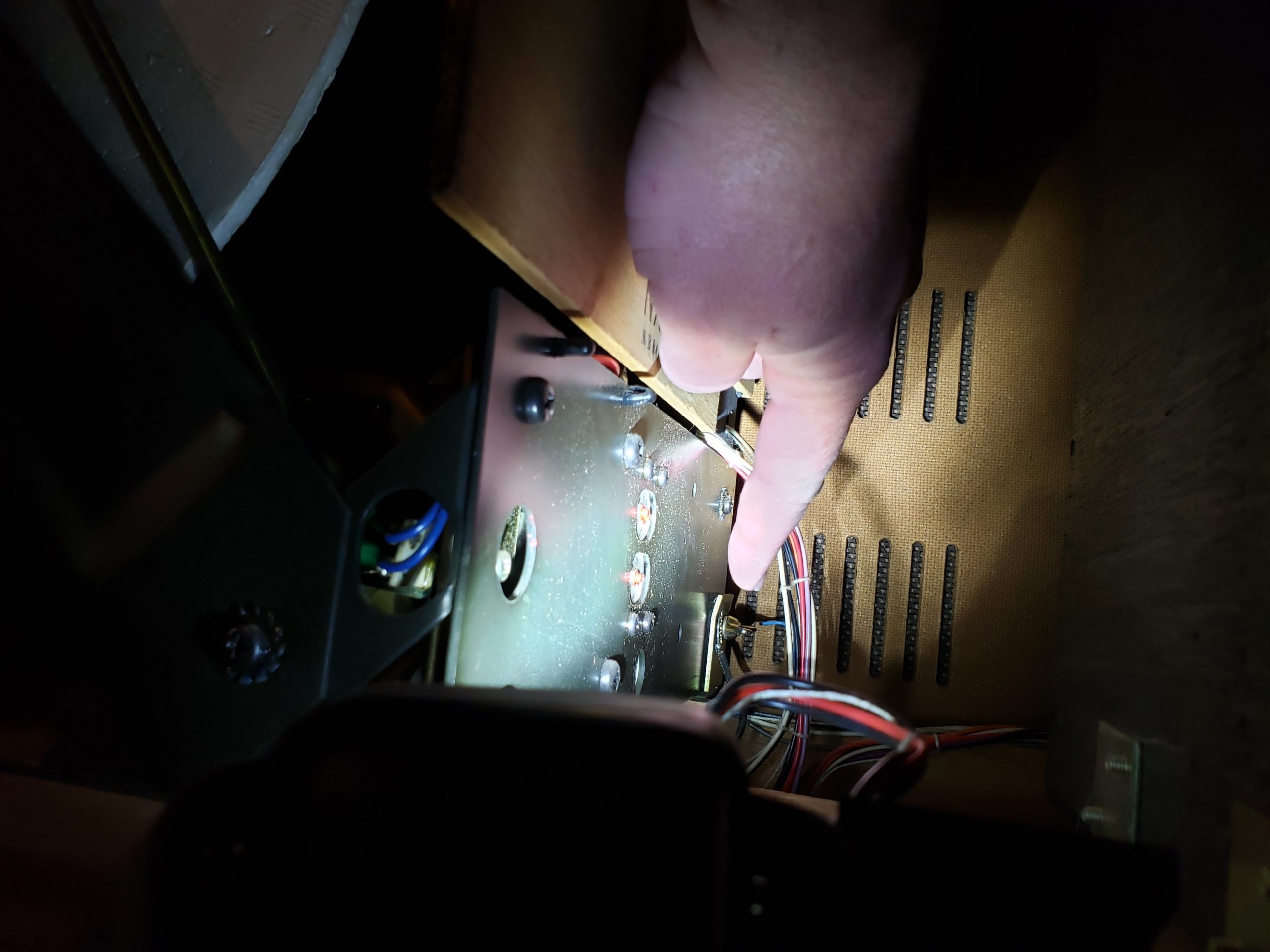
The wingscrew had been cross-threaded at some point on mine and it took pliers to get it out.
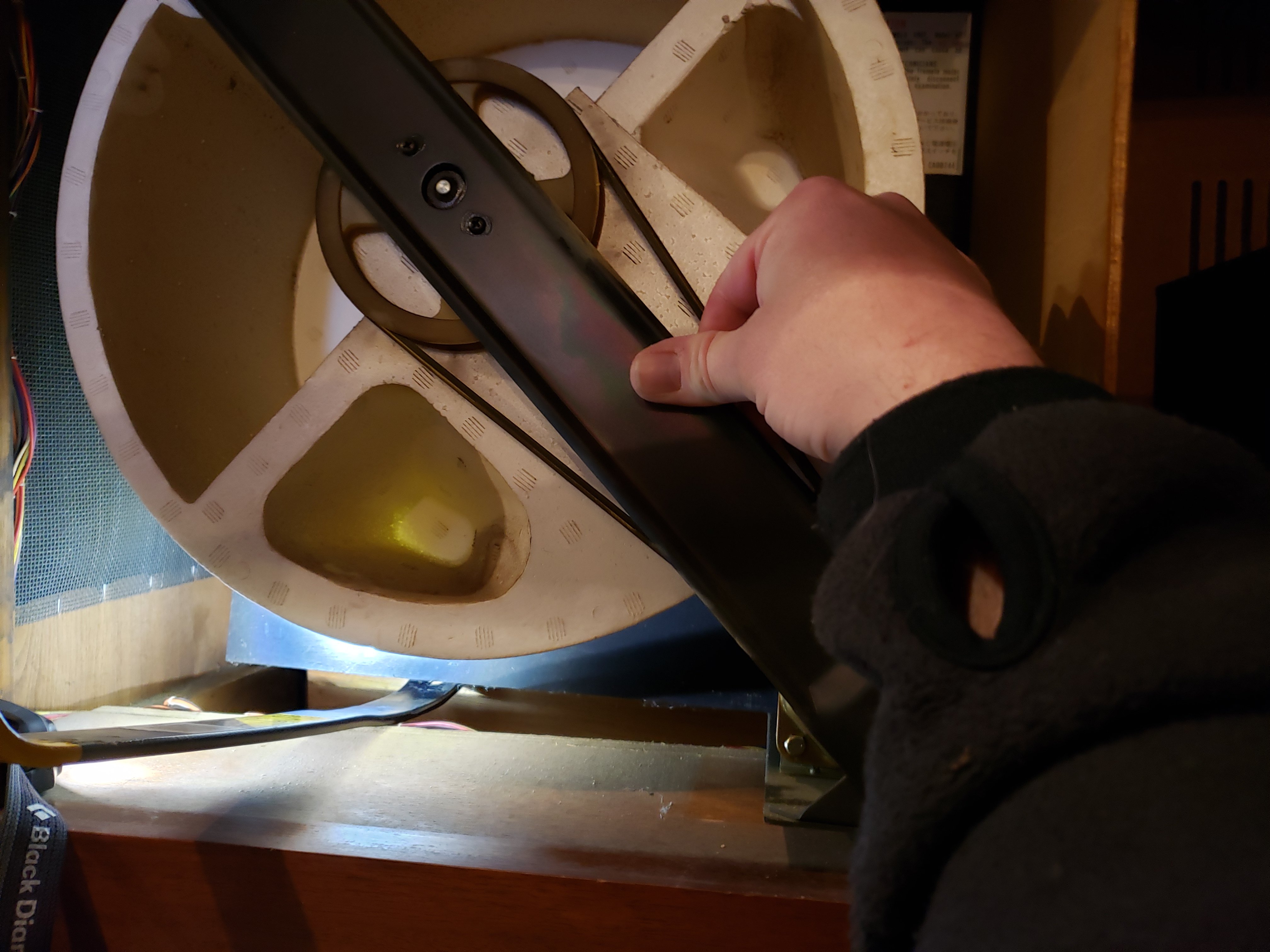
Once the screw is out and the connectors are disconnected, lift the tremolo assembly. It’s held in place with two pins on the assembly that are inserted in housings on the chassis. The unit is very heavy and the pins are pretty tight, so use a crowbar to lift the tremolo assembly up and off the pins.
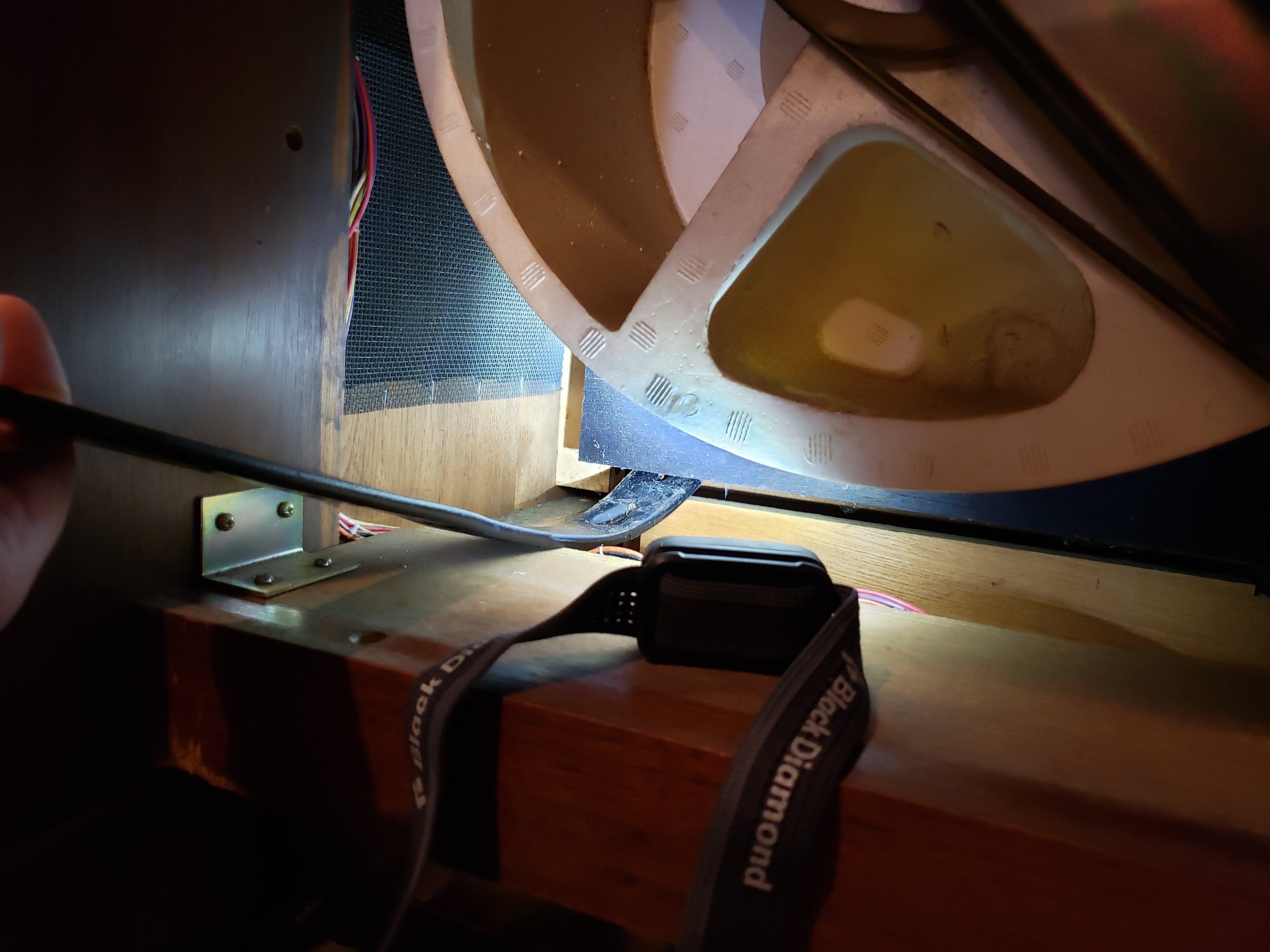
Slide the tremolo assembly out using the crowbar as a bridge.
Now you can remove the motor and motor control circuit.
Remove the Motor and Motor Control Circuit
There really isn’t a good way to work on the circuit board in situ, but the motor and circuit board are fairly easy to remove.
First, cut the cable ties that hold the wires going between the motor and circuit board. There might be a way to pop the cable tie retainers out from the assembly, but I couldn’t figure it out.
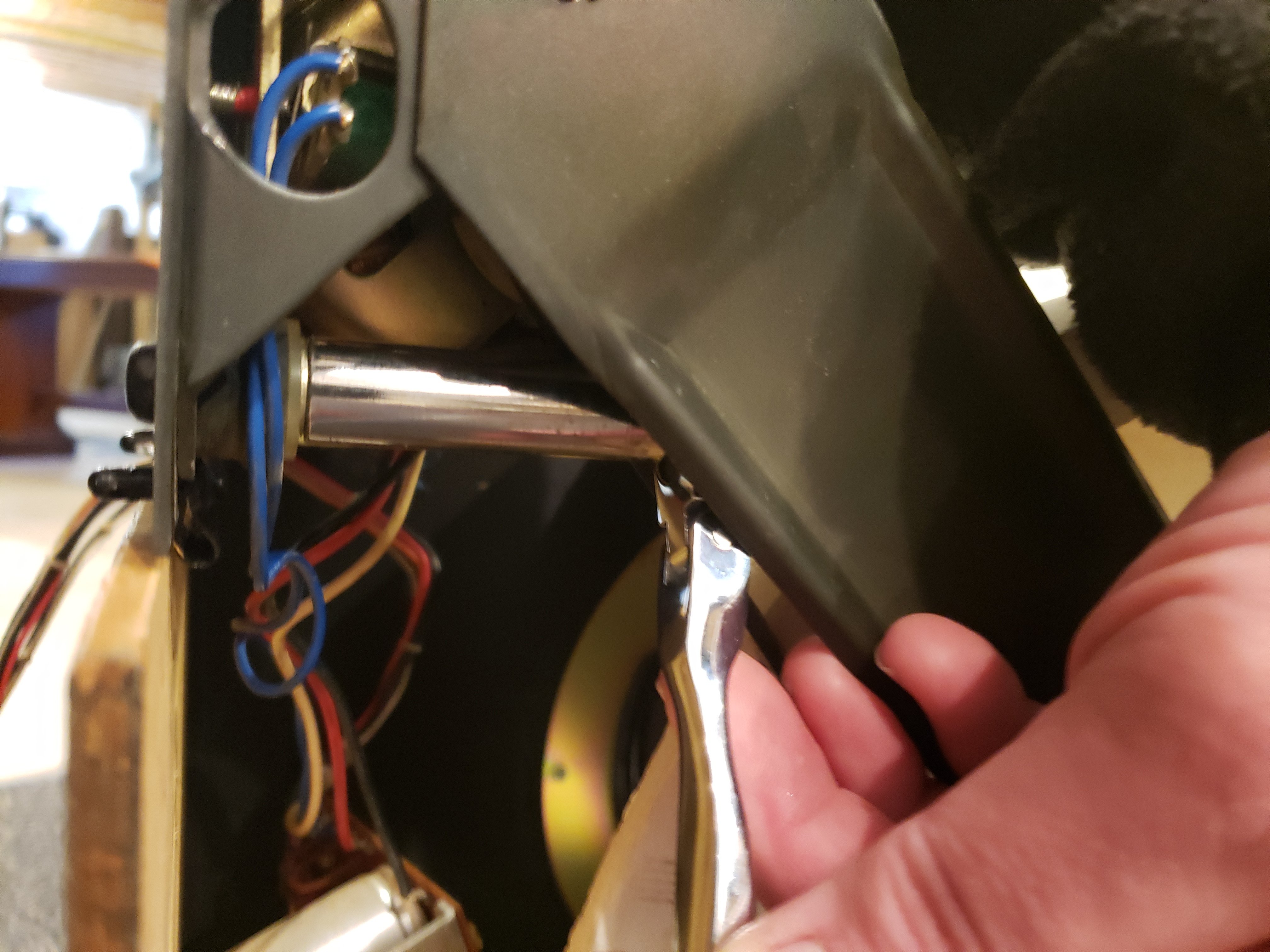
Release the wire ties holding the connector in place (in blue below).
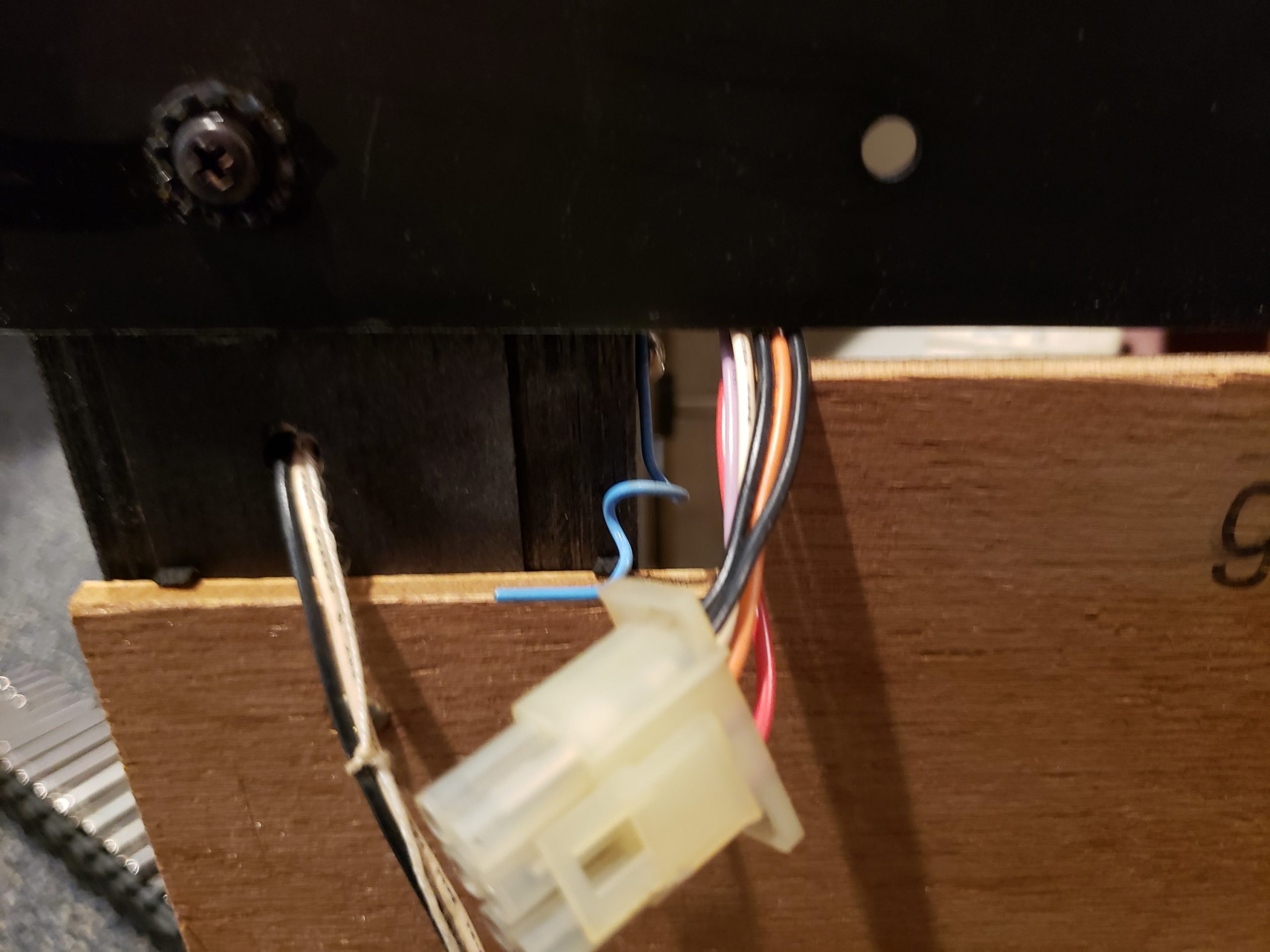
Slide the connector out so that it is on the same side as the motor and circuit board.
You can also remove the wood baffle to make things easier. I left it in place, but it’s easy to remove.
Unscrew the two screws holding the resistor circuit board in place. These are very tight JIS screws, so you might need an impact wrench.
Unscrew the controller circuit board (I forgot to take a picture of that). Then, remove the four bolts holding the motor in place. Be careful to not lose the washers behind the nuts.
Lift the belt off the motor pulley. The motor and motor circuit should now be free.
Repairing/Renovating the Motor and Motor Controller
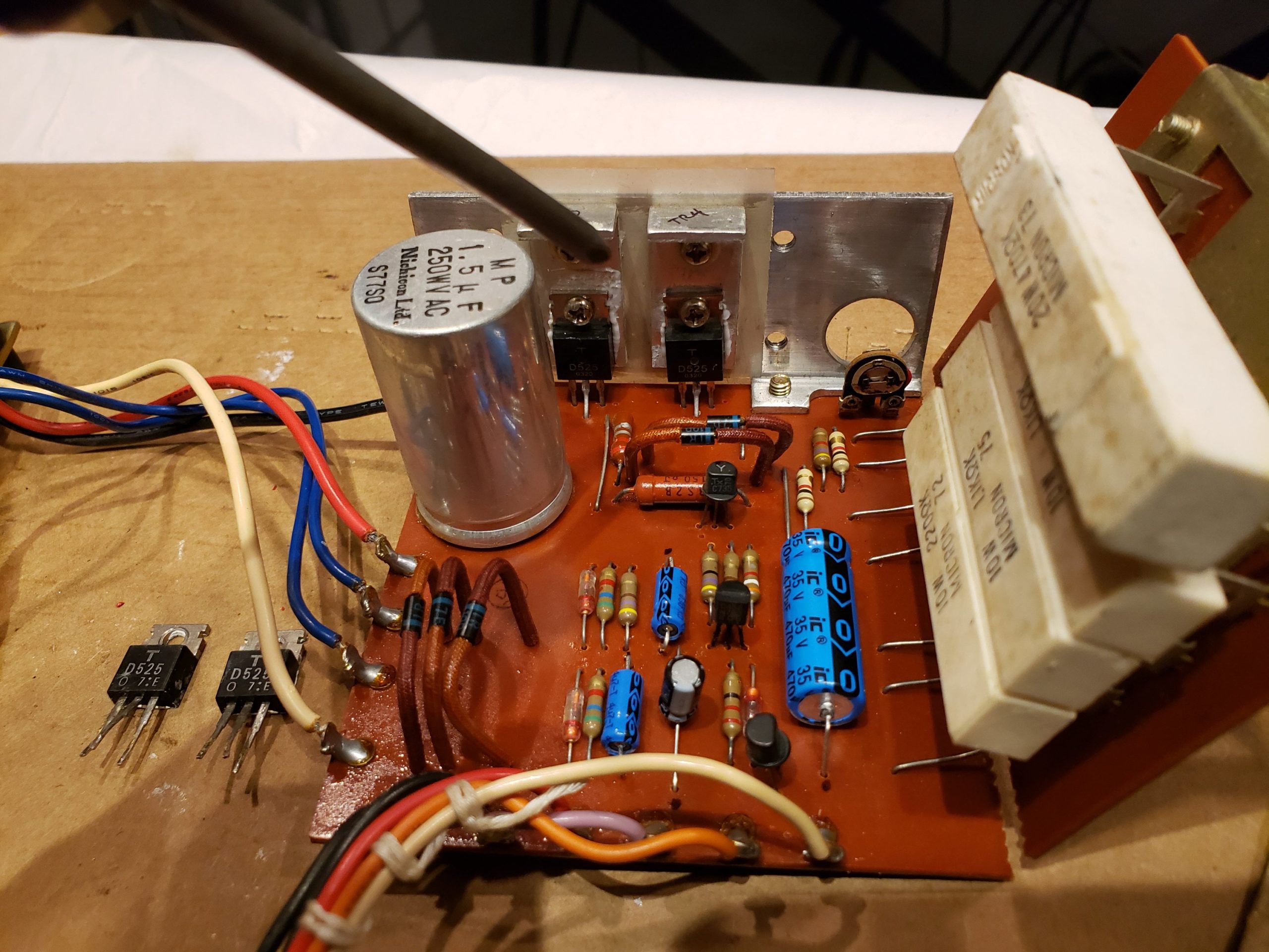
The most common problem is likely to be bad 2SD525 transistors which are the four TO-220 guys you see in the picture below. The two on the bench are bad.
The service manual online implies these are actually 2SC525s, which are the same thing in a different package. Perhaps Yamaha changed to the TO-220 package at some point?
Regardless, when these start to fail they cause the motor to run intermittently.
It’s a good idea to re-cap this while you’re in here. I didn’t replace the motor run capacitor but only because I didn’t have a good one handy. Also, please ignore my radial-leaded capacitor since I didn’t want to order an axial one.
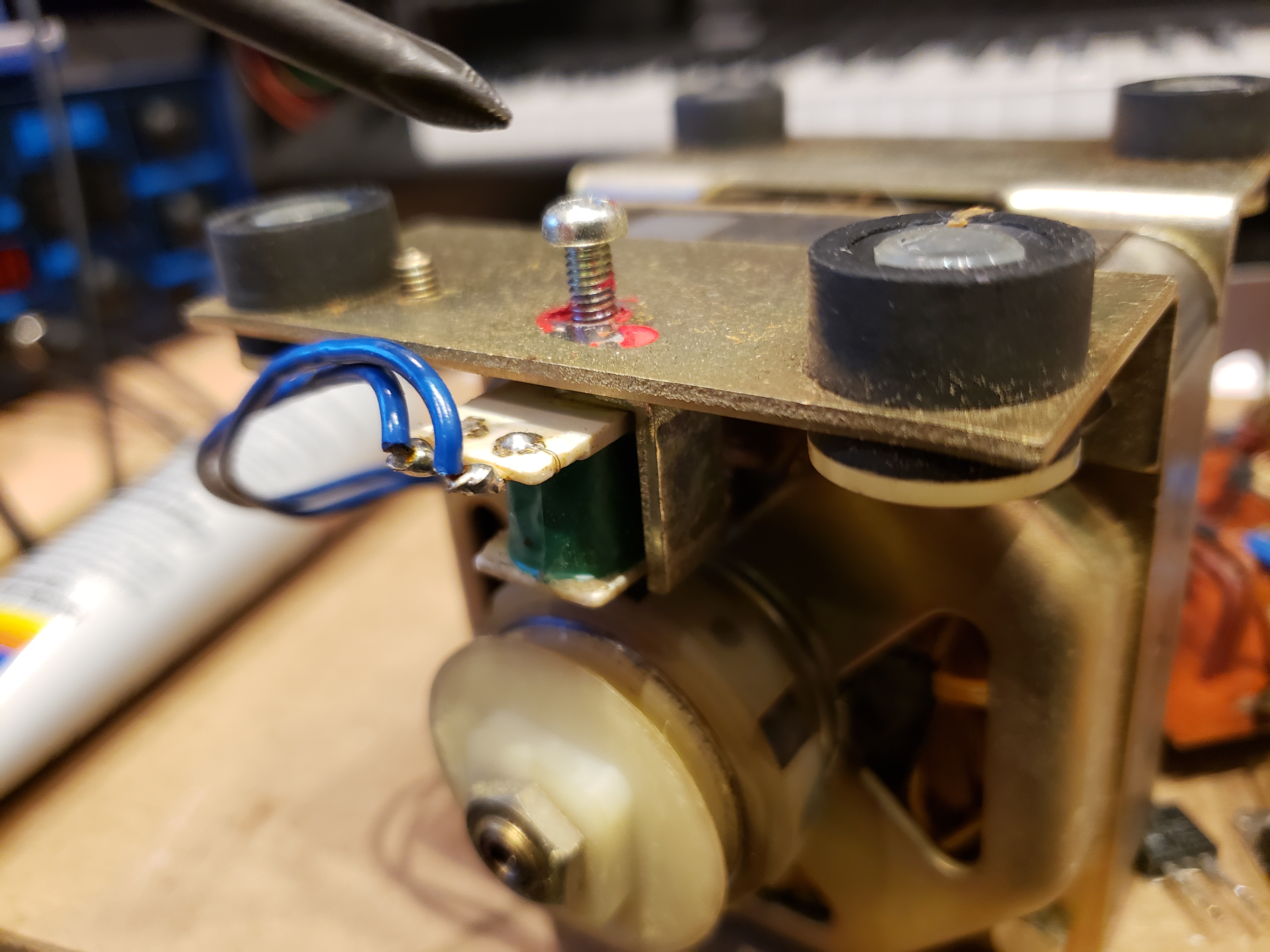
Another potential problem is the hall effect sensor. The screw I’m pointing to below controls the distance between the hall effect sensor and the rotor. If it’s too close then the motor is slower and more herky-jerky. If it’s too far then the motor spins too fast.
Other than these problems there isn’t anything particularly likely to go wrong.
Test and Adjust
Once the 2SD525s and capacitors have been replaced, you can test the motor without putting everything back together. Just re-connect the motor circuit connector and confirm that Celeste and Tremolo both work correctly.
Once you have confirmed smooth operation you can roughly adjust the hall effect sensor. But, adjust it again after putting everything back together since the rotor drum has a flywheel effect. Lock the screw with green Loctite.
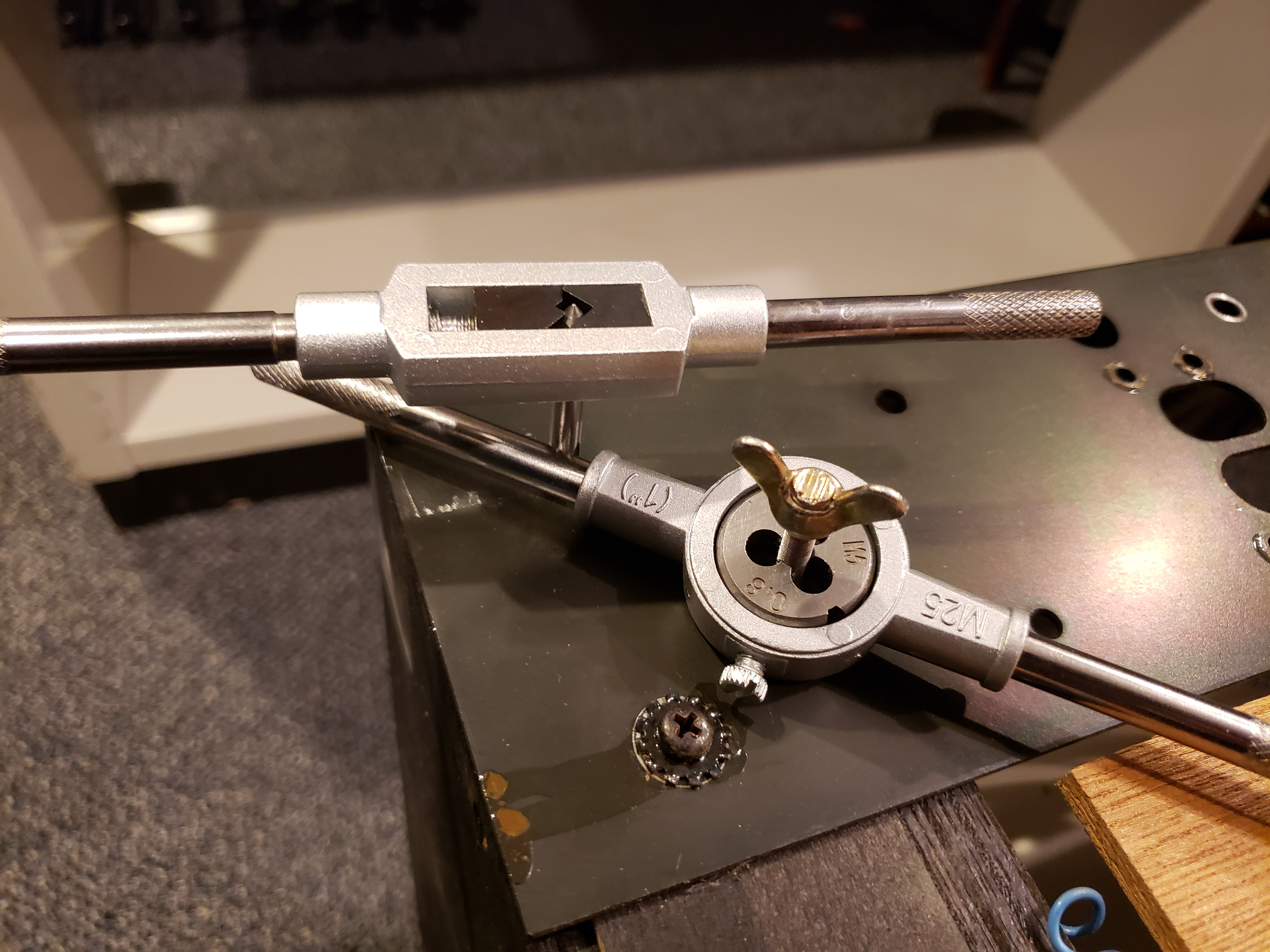
If you need to re-tap and thread your wingnut like I did, it’s a 5.0mm x 0.8 thread.
Reinstallation is the reverse of removal! Be sure to replace the cable ties that held the motor wires down. You can completely remove the old ties and replace them with regular cable ties.