When the good folks at 4×4 Connection (née Land Cruiser Connection) moved from Sterling, Va., to Winchester, Va., they had to get rid of a lot of stuff that was taking up space on the shelves. One item of which was a Weber 32/36 DGAV in good shape with the mounting brackets for the 2F motor.
So, I got this, a wiring harness, 3 various Aisans, and about 4 boxes of miscellaneous parts for $50—not a bad deal. The most important bit was the DGAV, of course. Since there’s one on the Triumph, and all three Fiats use Webers, I’ve gotten to know this carb fairly well. It’s extremely tunable, and seems to be dead reliable.
However, to install this carb one apparently needs a throttle pedal and cable from a 40. As a result, the DGAV sat around for a while until I finally ordered the parts. In the meantime, it seemed appropriate to go ahead and get the truck ready for the carb. In so doing it was apparent that this carb will work fine with the existing linkage. And that’s what this is all about.
- Remove the air cleaner and the associated vacuum lines.
- Remove all emissions controls on the driver’s fender (arrow 2, Figure 1). This whole assembly may be taken out as one unit, but don’t throw any of the parts away.
- Remove the steel vacuum lines which run along the front of the block behind the thermostat housing to carburettor/manifold area (arrow 3, Figure 1).
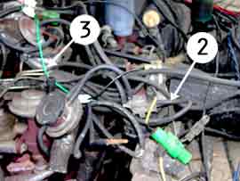
Figure 1 - Disconnect the carburettor linkages and vacuum lines. Disconnect steel fuel line and cap off to prevent leakage. Remove carb.
- If your air pump is still in use, remove the hose running from the air rail. This may be difficult to remove on the air rail side, so it may be taken off of the air pump side.
- Remove EGR assembly by removing two bolts on side of EGR unit, and two bolts each from the pipes going to the intake and exhaust manifolds. Do not throw away the gaskets!
- Remove the air rail. This will be very difficult to do, as the ports have most likely rust-welded themselves to the rail itself. If you’re reading these instructions in advance you can try to spray the nuts down with PB Blaster. However, it probably won’t have much of an affect due to the constant temperature changes that occur. Therefore, you may have to unscrew the ports from the block and simply accept that the rail will be destroyed in the process.
- Now you’re ready to start installation. First you must cap off the air rail ports. This was left as the last step previously to prevent garbage from entering the holes. Use 1/4″ pipe and 1/4″ pipe caps to plug the holes (see Figure 2).
- Bring an old port to the hardware store just to make sure you are getting the right thread (pipe thread). Wrap them in Teflon tape before installation.
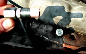
Figure 2- Prep the mating surface of the intake manifold. It’s also advisable to check that the surface is level, as this can be a source of leaks. I used a 3M abrasive disc to level a couple high spots.
-
- Create block-off plates for the EGR ports on the intake and exhaust manifolds.
I used electrical outlet blanking plates. They’re galvanized, and are thick enough to apply pressure to the gaskets.
Take the old gaskets and place them on the blanking plate (Figure 3,1). Arrange them so that they both fit, and spray paint the plate black. Once the paint is dry you’ll have a template (Figure 3,2).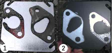
Figure 3
- Create block-off plates for the EGR ports on the intake and exhaust manifolds.
-
- You will need to file down a washer on one bolt holding the heat control valve in place (see insert in Figure 4). This is the one located closest to the carb mounting, and has the washer overlapping where the new carb fittings go.
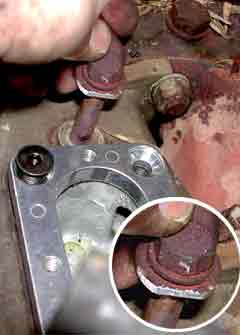
Figure 4
- You will need to file down a washer on one bolt holding the heat control valve in place (see insert in Figure 4). This is the one located closest to the carb mounting, and has the washer overlapping where the new carb fittings go.
-
- There are two mounting plates. The first (visible in Figure 4) attaches to the manifold and uses special hex bolts to hold it in place. The second attaches to that and has the studs to which the carb mounts. Both of these should be checked for flatness. Use a straight-edge on the bottom and top of the plates. Check along the mating surfaces (major and minor axes), and check diagonally across the plate. If it is not level, then it will have to be planed.
I simply placed heavy grit sand paper on a level concrete floor and did the planing by handa power sander was too inconsistent. Then, I followed up with 3M 220 grit Drywall Screens. Although not made for metal, these drywall screens provide a smooth finish with enough contour to ensure a sealing surface.
The other important bit is that the bolts holding the top plate to the bottom plate were too long on mine. Note: You must check this before installation. If they are too long then they will warp the bottom plate by pushing against the intake manifold. Replacement bolts are available at most any hardware store. (I brought the plates in, along with an Allen wrench to make sure the bolts won’t poke through).
- There are two mounting plates. The first (visible in Figure 4) attaches to the manifold and uses special hex bolts to hold it in place. The second attaches to that and has the studs to which the carb mounts. Both of these should be checked for flatness. Use a straight-edge on the bottom and top of the plates. Check along the mating surfaces (major and minor axes), and check diagonally across the plate. If it is not level, then it will have to be planed.
-
- It’s time to get everything ready. I placed gaskets and high-temp RTV between each of the plates, but not (ever) on the carb itself.
Place the carb on top of your plates and spacer. Attach one bolt on the side closest to the engine to hold the carb in place while you work on it.
- It’s time to get everything ready. I placed gaskets and high-temp RTV between each of the plates, but not (ever) on the carb itself.
- Place your throttle linkage plate on the carb in the same location as if it were on the Aisan. It should be a bit too large, but you can bend the tang in closer (see Figure 5,1).
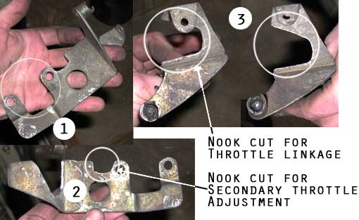
Figure 5  Cut a nook into the plate for the secondary throttle adjustment. This should allow the secondary throttle stop to move freely. See Figure 5, 2.
- Cut a larger nook into the plate on the lower section that has the return spring retainer. As the throttle linkage will have a new arc, this will allow the throttle linkage to swing freely. You may have to make adjustments to this once you have the linkage hooked up.
- Don’t worry about the arm being significantly thinner than it was before, as the spring doesn’t carry as much tension on it. This is still strong enough to provide a stable location for the return spring.
- Take the old throttle opener from the Aisan carb and remove the two tangs that acted as a stopper and opened the secondary. Figure 6, 1 shows both the part, and where to cut.
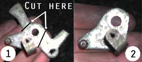
Figure 6
-
- Once completed, the throttle opener linkage should appear like Figure 6, 2.
-
- If there is already a throttle opener on the DGAV, remove this by bending the tang lock washer, and removing the 12mm nut. Replace the tang lock washer, nut, and bend the tang to secure the nut. Then, place in the following order an 8mm flat washer, the modified throttle opener linkage, an 8mm lock washer, and a nut of the same dimensions as the 12mm nut above. This is to prevent further binding of the throttle opener mechanism, and to securely fasten the opener linkage.
-
- Disconnect the vertical linkage going from the pedal assembly to the horizontal rod.
-
- Attach the linkage plate to the carb, and secure with 2 nuts.
-
- Connect the horizontal rod to the linkage plate, and connect the swing arm linkage to the throttle opener linkage and the horizontal rod. See Figure 7 for terms and setup.
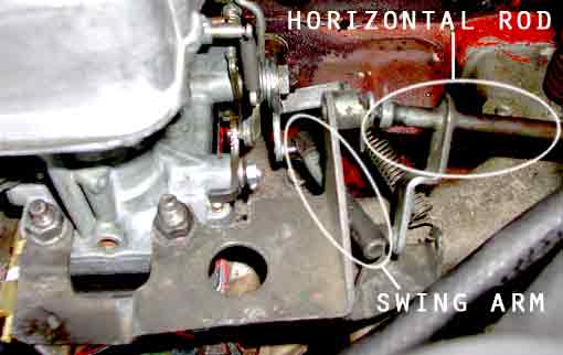
Figure 7
- Connect the horizontal rod to the linkage plate, and connect the swing arm linkage to the throttle opener linkage and the horizontal rod. See Figure 7 for terms and setup.
-
- Loosen the nut securing the throttle opener linkage to allow it to move freely on the opener mechanism.
- Reconnect the vertical linkage going from the pedal assembly.
- The tension in the pedal assembly should be enough to hold the throttle opener linkage in the location is should be. Tighten the nut holding the throttle opener linkage and rotate the horizontal rod.
Check to see that the throttle plates open completely and that the secondary throttle opens completely. If not, readjust either the location of the throttle opener linkage, or the length of the vertical linkage from the pedal assembly.
Have someone sit in the cab and press the throttle pedal all the way down to the floorboard. Again, the all the linkages should swing freely, and the throttle plates should open completely. Tip: Instead of looking in the barrel, you may check to see that the secondary throttle adjustment arm is hitting the adjusting screw for which you cut a nook in the throttle linkage plate. -
- Purchase a section of 5/16″ steel fuel line from the auto parts store. Bend this into roughly the same shape as the original fuel line.
-
- This is how I made my fuel connection, but there are other ways. Use the following brass hardware in the specified order to make the fuel line connection to the carb:
5/16″ compression to 1/4″ female pipe (FIP)
1/4″ nipple
1/4″ FIP to 1/8″ FIP bushing
1/8″ nipple
1/8″ street elbow
1/8″ x 1″ nipple
1/8″ street elbow
Use Teflon tape everywhere.
Figure 8 shows this basic setup, however, I use a Tee instead of one of the street elbows should I wish to add anything later.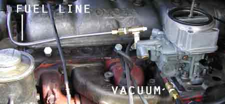
Figure 8
- This is how I made my fuel connection, but there are other ways. Use the following brass hardware in the specified order to make the fuel line connection to the carb:
-
- Add the following parts to obtain a manifold vacuum line (this will be needed for some emissions controls):
1/8″ street
1/8″ FIP to 1/4″ FIP bushing
1/4″ MIP to barbed pipe
See Figure 8 for attachment.
- Add the following parts to obtain a manifold vacuum line (this will be needed for some emissions controls):
-
- Replace the primary idle jet. The stock size is 60, which is a bit small for this engine. I’m using an 80, and it’s a scoche weak, but it also improves fuel economy. An 85 or 90 should be acceptable.
-
- Cap-off the distributor vacuum line on the carb.
-
- Attach a vacuum gauge to the manifold vacuum port on the carb base.
-
- Place a block or dowel of wood onto the choke plates to close them 3/4 to aid starting.
-
- The engine may take a while to start. Starting fluid may be used to aid pumping the float bowl up. Once it starts running it may be a bit rough, but that’s okay right now.
-
- Check for any leaks in your fuel line. Shut down the engine and correct if needed.
- Warm up engine completely and set idle and idle mixture as per the DGAV instructions. (Basics: Check mixture setting, set idle to 1000, check that fuel is flowing from the main venturi, set idle to 500 or until fuel stops flowing from main venturi. Adjust mixture screw 1/2 turn inwardif engine slows, then idle jet is too large. Reset mixture screw. Adjust 1/2 turn outwardif engine revs up, idle jet is too small. Set idle mixture until engine runs smoothly and steadily. Reset idle speed to 650.)
- Just about done! Take an old Vacuum Switching Valve (VSV) from the emissions controls and mount it the fender. Run one terminal to 12V switched, and the other to ground. Attach the advancer port vacuum line to the port of the VSV that is open when voltage is off. Attach the other VSV port to the advance on your distributor.
Ideally, this will cause vacuum advance when running, but when the engine is shut down you will cease to have vacuum. This will prevent dieseling, or run-on.
Figure 9 may help illustrate the setup. (The other vacuum parts are the EVAP system, and the A/C kick-up valve. Currently, the EVAP is not completely running, and the A/C is not setup at all).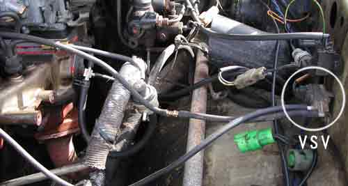
Figure 9
That’s it! If you’re ‘Cruiser is like mine you’ll notice a significant improvement in power and low-end torque. Previously it took an age for the truck to even start, regardless of whether the carb had been rebuilt or whether it was old. Now, it starts like it’s fuel injected.
One thing not mentioned in the instructions is that I also punched out my cat (-alytic converter, that is). This was a Cat-Back system, and it seemed to have good flow. However, the honeycomb fell apart (I guess it can’t take much abuse). It’s simple enough to do, but I wouldn’t waste a good cat on it. But, if you wanna, just take a long pipe and jab it into the input pipe. Eventually you’ll break apart the honeycomb and it’ll spill out.
There’s still some more work to do, including getting the EVAP system to work, and making sure fuel economy is decent for the highway while still have good low down pulling. I may end up experimenting with the emulsion tubes, but more likely there’s some time with air correctors in the future.
If you have any questions, please don’t hesitate to ask. My e-mail address is web@mphtower.com. Good luck!